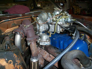
Machining Spring pocket on 200 head

NorfolkAndWaye

New member
Looking at machining the spring pocket on the 200 six head to accommodate a bit more installed height in a spring. They've already been machined flat, and cut for positive seals.

How deep can they be cut? Is there 40 thousandths, 100 thousandths, etc? What kind of depth can be had before you break into the intake port?
 
Welcome aboard, does your machine shop have a sonic tester to check thickness. What do you need for spring installed height?
WlbLkMj.jpg

Nu20J5v.jpg

Then we will go from there.
 
Ideally we'd get to a 1.800" installed height, but that's a pretty good stretch from the 1.625" height the spring sits at now.

Currently, there is a set of 0.030" thick spring locators under the spring, and the original step in the cast iron has been machined down to match the original spring seat. The guides have been machined for 0.500" positive seals.

The retainers being used sit dead level with the valve tip, so I'll probably grind 0.020" from the top of the retainer (not going to harm a thing) and hopefully drop the seat 0.100", but it doesn't look like there is much meat in the ports there. Maybe can get 0.075", which would get me to 1.700" installed height. Thinning the locator seat down another 0.020" could be done as well.

If things were ideal, I'd be able to just go get longer valves. However, the racing class doesn't allow for that...13's for 1300$, including the cost of the car. Total cost so far for this one...1240$, after the block machining. Ain't much money in this for makin' the springs sproing!
 
dhayum - seems like a 1/4 inch thick there?
What's on the CI/VI alu head thay are talking abt in the other thread? (for the dual spring instal)
:unsure:
 
"...Ain't much money in this..."
I thought Le Mons racing wuz killed by the C-19? Is that what ur doing Mr. Wayne?

W E L C O M E !!!
to our site
 
How much cam are you using ? You should be able to find a spring that will work without major machining.
 
Not much cam. The problem is TOO much spring! Need to get installed height taller so the spring pressure comes down.

Cam is Howards Cams 0.470" lift/275* duration, needs about 280lbs open pressure at 7000rpm, with the 12-18PSI of boost we'll be running. 250lbs of open pressure would be fine to 7K normally.

Using the LS1 retainers and beehive springs will bring the valvetrain mass down quite a bit, so the hydraulic lifters shouldn't have any issues with the RPM. Also...they're free and free is good.

LYuJ02yh.jpg


hfJc1mJh.jpg


Still have to work out the carb linkage, and make a power valve cover that I can port to manifold pressure for boost enrichment. Carb is a 1.21 venturi Autolite 2100 that came from a 429 Galaxie Police model, (not an interceptor!) and has been internally modified into a 4-circuit carb. Idle, separated transfer slot circuit, Main, and boost enrichment.
 
Draw-thru turbocharging was always at the forefront of small displacement HiPo homebuilds. . What does the setup fit in?. Does it have a car build waiting?. Straight forward clean build should be a lot of fun road tuning .

Interested in how you provide for enrichment/ PV boost reference on 2100 and is the ign. timing controlled?. 'used a similar concept BOP derived draw-thru setup on a 250 in a Maverick. Specific Qjet carb used external PV port for enrichment under boost and ign. was 'locked out' @ 26dg. OEM 250 head has back cut valves, 302 springs, ARP hd bolts @ 62cc chambers - stock block/cam. Ran well with 5-10 lbs boost. Optimistic at @ 15 lbs of boost caused piston ring lands to give way.

. .

have safe fun


Built Draw-Thru turbo setups looks right out of Ak Miller shop.
 
70 Maverick.

Drill and block power valve vacuum port to the void between throttle bores with an 8-32 set screw. Drill out PVCR's and tap for 8-32 set screws, drill the set screw with appropriate PCVR "boost jets". Fit 2"Hg power valve, and port the power valve cover to manifold pressure, so power valve sees manifold pressure and not carb venturi pressure.

Now, you have idle passages that cover up to 1800RPM, main jets that cover 1600RPM to the top of the tach, and the PVCR's that are adding fuel from just before the boost threshold all the way into boost. You will still have to tune main jet and PVCR's for any change in boost pressure, and it'll only work up to about 350HP, because, well...that's about the 14psi boost mark for this turbo. On top of that fuel distribution is going to be a nightmare in this log intake, so I don't expect ring lands to live long.

On the plus side, fuel atomization is extremely good with a draw-through setup, chemical intercooling pulls double duty in helping that happen. Contrary to popular belief, fuel "sling-out" doesn't actually become an issue at mid-to-high boost levels-the heat of compression tends to make sure any fuel that would be "slung-out" of suspension by centripetal forces instead vaporizes. The tau-layer tends to remain constant above about 8psi, not highly variable as many people suggest.

The issue with the log manifold is that the center of the manifold remains hot, wheras you get toward the ends and fuel tends to start falling out of suspension-less turbulent air and heat tends to allow a thicker tau-layer, so fueling response is damped. This means that as you ramp into boost, cylinders 1 and 6 will initially go lean, then richen up, then go very rich on the transition back to vacuum, compared to cylinders 3 and 4.

If the manifold was seperated at cylinders 3 and 4, into two seperate (no crossover at all) plenum spaces, then this issue tends to go away. I will likely be experimenting with this, but probably not on this head, as it's not cracked.

On your piston issue-breaking that 2nd ring land isn't a lean-out problem, it's a ring gap issue. Gap your second-ring larger than the first by 4 to 6 thousandths, and that issue goes away. Detonation will start to soften that top ring land on the piston, you'll see rolled over corners, then broken lands. Usually you see the rolled corner, and broken lands at the same time, cuz the rolled corners and melty bits don't tend to shout "I'm dickered!" until you pull it apart for the broken ring lands!
 
Chad, I really don't understand your post. Care to elaborate?

Also I forgot to mention the ignition system-Coil pack and EDIS-6 setup, using the 2.3L Lima distributor delete with the oil pump gear swapped over. That also reminds me I need to get the controller booted up again and update the firmware, this old thing is a bit worse for wear!
 
Oh boy, speakin of off topic, here I go.
for me this is now a thread for
https://fordsix.com/viewforum.php?f=79
/AND/
https://fordsix.com/viewforum.php?f=22

I like it when I can scan the boards here, read a thread title that hasa clear indication of its content, search down into all U glorious experts (I'm a shade tree mechanic) input, and get some definitive infotmation I can use on my or the bosses customer's vehicles. We do not have the staff time on the site to make a compendium of stickies, sort & categorize them, and so forth. Increasingly I am forced to use a name I trust as expert and go scan evert post he or one of the other's have put up here for close to 30 yrs. I fear to ask4 "order in the court" as this is a friendly bd and folks tend to see that as not helpful when I am trying, instead, to B helpful.
Thnx 4 askin.
What say you?

https://fordsix.com/viewforum.php?f=90

https://fordsix.com/viewforum.php?f=71
 
I like to use the exhaust port divider that they sell...It helps retard the heating of the intake manifold, not really for the flow thing.
 
So, got the spring pockets machined down 90 thou with a borrowed tool. Spring pressures now right on at 92lbs seat, 270lbs open. No signs of hitting water or intake ports, everything looks good. Springs are standard LS1 factory springs.

Ground the LS1 retainers 0.030" on top to make sure we have clearance for the valve tips to the rocker tips, without hitting the retainers.

Next on the list is getting a replacement wastegate actuator. The factory one on the turbo is minimum 17lbs...that's more than we want to start with. I'll probably hack one together off of a Volvo or something.

After that, the EDIS coil pack and crank sensor have to be mounted-we've got the trigger wheel mounted on the damper, just need to make a new alternator mount for the GM alternator and integrate the crank sensor mount into it. I got the EDIS controller built, programmed and went to stuff it down in the nice aluminum project box, and the box is 5mm too short.

Next time I get to work on this, I'll get some photos.
 
Back
Top