Turbo 300 Install - 69 F100 - VIDEO

A

Anonymous

Guest
Thought I'd share some pics on what I've been doing the last 2 weeks :D

Donor engine 89 F150:

http://www.wiricksgarage.com/public_pics/89_300.JPG

Some cleaning and some paint:

http://www.wiricksgarage.com/public_pic ... _paint.JPG

Building a turbo manifold:

http://www.wiricksgarage.com/public_pic ... nifold.JPG

Modding the intake:

http://www.wiricksgarage.com/public_pic ... welded.JPG

Engine going into my truck:

http://www.wiricksgarage.com/public_pic ... _in_69.JPG

How it sits today:

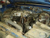
http://www.wiricksgarage.com/public_pic ... engine.JPG


Ok, so that's 6 pics per the rules (does the limit apply to linked pics?), and it pretty much brings it up to date, though I don't have a good one in there of the turbo itself.

I've got an old Megasquirt 1 laying around that I'll use to get it running for now. Mainly fuel system, cooling and electrical left to do
 
The six pics rule if for when you directly upload them into a thread, the software setting will not allow you to do more than 6 per single post. When you link to pictures hosted on another site like you have done you can post as many as you like (and we like them a lot)
This picture doesn't fit the guidelines.. (600x450 max resolution)
http://www.wiricksgarage.com/public_pics/89_300.JPG
so I downloaded it, resized it and embedded it...
89_300.jpg
The rest are all perfectly acceptable for linking to. This also shows the difference in what a linked picture looks like versus an uploaded/embedded.
300_some_paint.JPG

Turbo_manifold.JPG

300_Intake_side_welded.JPG

I do have a question about this one.. your picture says 'going in the '69' but in this picture it isn't painted all pretty like the one with 'some paint' or the other one where it is in the pickup with the intake mounted. What's up with that?
300_going_in_69.JPG

300_intake_on_engine.JPG


Tell me more about the modding that you did to the intake.. it looks like you are using a different throttle body and have plugged at least one other hole. Did the aluminum machine/weld easily? And how come no picture of the turbo installed? We like motor porn around here... but a motor with the turbo OFF just isn't as sexy as it is with one ON... :rolflmao:

-ron
 
CoupeBoy,
Thanks for clarifying the rules, one more question about that though. Do I need to have the pictures 600x450 to link to them? The reason I didn't want to post them inline is because I had already re-sized them for another forum that required 640 width, and didn't take the time to re-size them again. If I post inline I'll get them 600x450 or less for sure.

To answer your first question, that pic of the engine going in the truck actually is all fancy painted and stuff, its just a terrible picture, not sure why it turned out so bad. I used it though because it shows the truck a little and most of my pics so far just show the engine.

Second question, I am using a GM MPFI throttle body mostly because I had it laying around and it was a nice way to get the intake down to 1 hole. I thought it would be an easier way to go than fab a dual port box or a Y tube for the two port throttle body, plus it makes the run to the turbo cleaner (shorter) than having the throttle body on the far side of the intake. Turns out it was just a difficult fab wise as the intake is "dual plane" and has a divider between the throttle body barrels so 3 cyls run of each barrel. I had to cut that out and smooth the inside so all 6 can breath off of the one port.

The cast aluminium intake isn't a great casting turns out. I hit a lot of small porosities while welding, nothing that was extreme, but the welds don't look as pretty :( Not that I'm awesome at the TIG anyway. I just used a band-saw and die grinder on the intake so not much machining experience there. The parts I welded on were 6061 billet I machined with my (diy) CNC mill, they machined just fine, as one would expect from billet stock ;)

Finally in that last pic the turbo is actually installed, its just on the other side of the engine. I have more pics so I'll get some more up soon.
 
Ok, here are more pics of what I did to the intake:

Roughly drill out the front of the intake with a hole saw:
Intake_front_out.JPG


Use a band-saw to cut off the original TB and EGR mount, then a saws all to cut out the divider:
Intake_rough_middle_out.JPG


Weld on the new intake tube, and port the hole to match:
Intake_part_front.JPG


Machine a 1/2" aluminium plate to fit the new TB and weld it on the new pipe, die grind out the rest of the internal divider, die grind back the thin spots around where the original TB mount was cut off, weld a plate in the old hole, drill and tap mount holes for the new TB and viola you get pic number 4 above!
 
Here are the pics of how the engine sits today. Yesterday I welded up the tube between the TB and the turbo (yes I know, no IC for now). Today I got the stainless coupler clamps in the mail, put them on, and cleaned up the original fuel lines that attach to the fuel rail. You know I actually like the OEM nylon line, I understand why a lot of guys don't but if you have good splices you can bend and splice that stuff with only a heat gun. I just wish there were more adapter fittings available. There are also some junk splices on the market that will leak no matter how good you are with them. But I digress, we wanted more pics :)

Turbo_300_Side.JPG


Turbo_300_Front.JPG


And a pic of the truck its in. Not much to look at from the outside, but its pretty straight and very little rust. I put new wheels on the front recently, but am waiting till I get new tires before doing the back

69_F100_Side.JPG


Finally I got my fuse/relay box in the mail today. Its an e-bay purchase out of 98 Taurus. Price was right and it had a decent number of fuse and relay spots for the truck. Let the wiring begin :eek:

Fuse_Box.JPG
 
Question. In the Turbo_300_Front.JPG pic above you can see that the turbo intake piping gets pretty darn close to the exhaust, I was planning on fabbing a stainless heat shield for that area, but am open to better ideas? Would header wrap work way better? I don't think I can get a tighter bend in there, although I don't suppose the first 6" or so of that tube has to be that large in diameter. Thoughts?
 
The picture size is limited to 600x400 whether you embed them or whether you link to them. For embedded I get it, they are coming from the server and fordsix has to pay for that bandwidth. But for third party hosted images, the only way it ever made sense was if we were worrying about members on low bandwidth. Since the images are hosted on another server they in no way impact the network bandwidth to fordsix. (but I'm not bitter...)

About the close proximity, I'd throw a heat shield in there. If it was good enough for my old motorcycles to keep my leg from burning, it should be good enough to keep the direct heat away.

blah, blah, blah, if you ceramic coated the exhaust manifolds and pipe from the manifolds to the turbo and then put on a turbo wrap you would have a lot less heat.. (now if only that were free) :banghead:

Header wrap really shouldn't be an issue if you used it there either, but if I had to guess (and I sort of do here) I would think that taking that air cleaner all the way to the front of the vehicle and pulling in cold air would probably be better use of space/tools to keep cool air coming in.

Looking good!
 
Been working on this as time permits, and finally got it running today (not driving or anything). The wiring is mostly done, there's no cooling system, no driveshaft, no gas pedal... One step at a time ;) Anyway, after working out a couple of typical wiring bugs, I still only had intermittent spark. Finding out that it was the Megasquirt ignition input putting too much load on the PIP signal from the TFI took a while. After swapping polarity on the ignition circuit it fired right up! I'll try to get more pics soon.
 
I would think that taking that air cleaner all the way to the front of the vehicle and pulling in cold air would probably be better use of space/tools to keep cool air coming in.

Totally agreed, I just had that piece laying around from another project and it fit, but once I get some more 4" tubing the intake routing will be improved.

The thing with the heat shielding is the silicone coupler that couples the intake pipe to the turbo. It ended up pretty close to the exhaust and I don't really want to burn the junk out of it.
 
Ok, managed to calibrate the temp sensors today, install the wastegate and hook up power steering lines. Made it short vid of it running this time so you can see. Its pig rich, I haven't done any tuning save to get it to idle, it doesn't have a throttle position sensor hooked up yet, and since I can rev it you know its rich.

Disclaimer - while fairly short the vid is still 20MB, so it takes a minute to get.
http://www.wiricksgarage.com/public_pics/300_Early_Statup.AVI
 
Just watched this video about ten times!

Awesome build...

Whats the turbo and wastegate from?

I notice you addressed the intercooler above, what are your plans for it??
 
The turbo, wategate and BOV are all from a turbo VW project I had going in 2008. It turned out to be an awsome engine, but the car never materialized, thus the engine never got turbocharged. The turbo was going to be a bit big for the 2165cc engine, but it was drag race only, and I think it'll be a tad small for this application, but a good start to get all the systems worked out. Everything is cheapo ebay stuff.

The turbo itself is a T3/T4OE .63 AR turbine housing. The compresser measures out at something like a 44 trim. So, in "theory" it should be capable of something like 300 hp around 15 psi, tho I understand that w/o raising the octane in some form a stock engine will only tolerate 10-11 psi safely. The turbo should come in quick and be out of breath by 4000 rpm. The wastegate is only a 38mm so I have some concerns about boost creep, but there's only one way to tell for sure.

When the truck crosses the line to "nice" I have another 300 stripped down and decked, ready for bore and hone and build for a turbo. At that time I'll evaluate the performance of the pieces I used this time around and make improvements from here. Might as well have some fun with what I've got right? :D My end goal is a power/weight ratio in the 12 second range, which I estimate at around 400 hp. With the NP435 it will never drive a 12 second run at the strip, but will be what I want on the street. This will require a different turbo (along with the new engine) and I expect it will be an OEM unit from a diesel.

I don't have any particular plans for the intercooler save that I plan to install one. I realize that my primary use for the truck will be commuting to work and running errands so it will be an air-to-air intercooler. The available space between the radiator and the grill is very wide but pretty short w/o doing extensive relocation. I will probably build someting or have something built to fit the space available.

probably way too much info, but there it is
 
Update of progress over the last few days.

I made a mount for the megasquirt, it goes right behind where the choke cable was (since its not needed now), and barely fits between the winshield wiper motor and the steering column support. I have plans to eventually make a fake choke knob with a built in USB port that accesses the megasquirt to tune it.

Megasquirt_Mount.JPG


I also shortened the driveshaft, not much exciting there. Its a 2 piece unit and I shortened the section between the transmission and carrier bearing.

short%20driveshaft.JPG


I am changing the alternator over to the driver's side so that I don't need the huge passenger side accessory bracket at all. This means re-routing the belt, which means the water pump needs to be standard rotation and have a ribbed pulley instead of a smooth one. Thankfully the old style water pump is the correct rotation and I happened to have a ribbed pulley of similar diameter off of an 85 ranger 2.3L. To make it all fit I needed to custom shorten a radiator fan spacer to give the correct offset. These are straight veined water pumps so I could probably turn the stock one either way, but the old style one has the correct bolt pattern on its flange anyway.

Water_pump_spacer.JPG
 
The other thing I did recently was weld up the turbo downpipe. I still need to attach a pipe for the wastegate dump, add an O2 bung, and fab a support strap so its not all hanging off the turbo. It took quite a while to get it to fit right, not a lot of room for the 3.5" pipe. I made it out of a used exhaust system from a 6.0 powerstroke, that the owner had upgraded. I ordered some heat shielding for the heater hoses and intake this morning, hopefully I can get the cooling system in soon.

Turbo_Downpipe.JPG


Turbo_downpipe1.JPG


Turbo_downpipe3.JPG
 
REALLY LIKE YOUR BUILD! Your mods. on the intake are interesting. Like to hear how she performs on the road. Im no expert, but i do worry for your Y-pipe. You might have an issue with expansion, & it might crack. Over time ?
 
Sorry I haven't been on here in a while. Here's what I've been up to (truck wise at least):

I finished modding my old megasquirt so that it will be capable of running the turbo wastegate and electric fans. I also re-designed the rpm input to work better with the TFI PIP signal:

Final_Megasquirt_Mods_Small.JPG


I added a support to my downpipe and installed a stainless magnaflow muffler:

Exhaust_Support_Small.JPG

Stainless_Muffler_Small.JPG
 
Back
Top