1995 EFI 300 turbo build

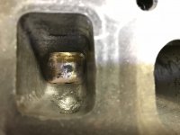
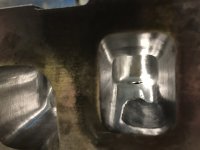
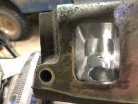
Tonight I finished polishing the 5 remaining combustion chambers with the 120 grit buffing pad. Then I went back to the first one and hit it with the 180 grit pad. I can’t really tell a difference so I’m not sure I’m going to do the rest. In the pic below, the one on the right is the 180 and the one on the left is 120.
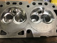
50451FC1-B0EB-4961-B5D5-EBDC21AED8C6.jpeg

I still need to work in the exhaust ports some more.

In unrelated news, I was thinking about shift point a little more and remembered the first gen Lightnings. I did some research and confirmed that they had a 5000rpm shift point. So by getting on of those ECMs I should be able to have a 5000rpm shift point instead of 4500. I’m not sure if it’s appropriate for this build or not, but at least it’s something I can consider.... especially since I’m still in the planning phase. Is it worth it? Will it make a large difference? I’m not sure yet. Any thoughts anyone?
 
Your shift point or rpm limit determines the turbo compressor size and engine horsepower.
Considerable difference between 4500 and 5000 rpm.
You also push the limit of a cast piston.
 
pmuller9":1paie3np said:
Considerable difference between 4500 and 5000 rpm.
You also push the limit of a cast piston.

Yeah, I guess I should have just done the math. 350ft-lbs @ 4500 = 300hp, whereas 350ft-lbs @ 5000 = 333hp. I'm just not sure what affect that will have on the overall curve. I guess I should download a desktop dyno and start trying some different combos to see what makes the most sense. You statement about the piston is something I was really looking for though - wondering how much more stress the engine sees going from 4500 to 5000. What about valve size? Would the 1.84/1.60 combo work similarly at 4500 and 5000?
 
Maximum "G" force on the piston and rod occurs at TDC at the end of the exhaust stroke.
The "G" force at BDC is about half the TDC force.
The "G" force is proportional to the square of the RPM.
Going from 4500 to 5000 rpm is a 23% increase in "G" force.

The larger valve head with porting and a non-log exhaust manifold extends the possible power band well after 5000 rpms.
 
pmuller9":3r3s9kr1 said:
Going from 4500 to 5000 rpm is a 23% increase in "G" force.

Great info! I was going to ask you about the rods and how close to the danger zone I'm getting on the 300 rods with the oiling hole, but then I remembered Sick6's build. He was pushing more RPM than I will be and he had a stock EFI bottom ends (including non-hyper pistons). So perhaps I'm ok with the 5000rpm limit then.

Do you have any recommendations for software or websites or books that can help me make the next decisions? I'm not even sure what a reasonable power expectation is for this thing so I can play around with turbo compressor maps. And I'm pretty much clueless on cam selection other than the specs you originally shared, but that was based on a 4500rpm limit. I used to think I could make a cam selection based on .050 duration and LSA, but seeing the posts you have made regarding the relations ship of Advertised Duration in relation to .050 duration and LSA and intake lobe centerline shows me that I have a lot to understand still......but I'm trying.

I'd like to shoot for the 5000rpm limit I think because I still haven't shaken the forumitis and it's exciting to chase a higher power number. HOWEVER, am I going to give up much power down low by going after that 5000rpm power? I don't want it to be soft on the bottom end just to gain some more on the top.
 
This is the most informative software you can work with to get a good overview of what to expect with different changes.
http://www.turbos.bwauto.com/aftermarke ... sin=92044&

I have it set up with Volumetric Efficiency that is close to what you would expect with your head work and a little larger came than previously discussed.
I also figured in an Air to Air intercooler at 60% efficiency.
Boost is set at 10 psi with full boost in at 3000 rpm.

Play with different settings and we can discuss your thoughts latter.
Just have fun!
 
Awesome, thank you! I will for sure play with this tonight. Keep up helping like this and you'll for sure end up on this year's Christmas card list! :D
 
I fumbled around for probably 30 minutes and then I finally noticed the tutorial videos at the bottom - those were really helpful. I've played around some and it's looking like the HX40 is actually a decent match for the engine, but I'm not 100% dialed in yet. If it does work, then I have a decision to make: do I buy the same wheels that I bought for the HX40 on my diesel or do I just move the diesel's turbo to the 300 and finally try the BW S300 I've been wanting to try on the diesel? It's going to cost about $350 in parts to fix the HX40 and closer to $600 to get an S300. After I play around with the 300 in MatchBot a little more I'll put the specs for the 6.5 diesel in there and see if I'll gain anything by running the S300.....but now I'm getting off-topic. This is a really cool tool, thanks!
 
Ok, I've done some playing on that MatchBot and feel like I've come up with a pretty good combo. I noticed that in the initial setup that you sent me the points weren't spread very much over the Compressor map regardless of which compressor I tried. So I started playing with boost and found that as I increased the boost the plot points spread further into the maps. This was before I watched the tutorial vids. Then I watched those and then understood better how you're supposed to update boost, compressor and turbine. So I kept iterating and iterating and I think I have a decent combo (I think). I ended up with a peak of 20psi because that was my initial goal and because I liked how the plot points looked on the compressor maps. I'm not sure if 20psi is reasonable, but as I recall Sick6 was running that and more, so I don't think it's that far off. If this is a real setup then HOLY CRAP that is a ton of torque!! That's actually kind of scary and makes me think of all the things downstream that may start breaking. :shock:

So what do you think, does this look like a reasonable setup?
http://www.turbos.borgwarner.com/go/GG4XR4

I have tried looking for HX40 maps and for some reason it appears that the compressor maps aren't accurate (I saw on a couple forums that a few people had that same feeling). The maps don't match the claimed flow in lb/min that the Holset site says they do. I still think an HX40 isn't far off and in the spirit of keeping this a budget-ish build it's still tempting to try the HX40 even if it isn't optimal. That could actually be fun: install the HX40, hit the dyno and drag strip and use that information along with recorded sensor data with the Megasquirt to evaluate how well the turbo is matched (or not matched). Then I can decide whether I want another unit or not.

I'm interested to hear what you think!
 
I thought I saw someone on here (maybe it was you PMuller) recommend bringing the bowl all the way out to the cylinder wall?

Is the Heart shape just for the "fast burn"?

If so which is "better" and why?
 
clintonvillian":k8glabgk said:
I thought I saw someone on here (maybe it was you PMuller) recommend bringing the bowl all the way out to the cylinder wall?

Is the Heart shape just for the "fast burn"?

If so which is "better" and why?

I don't really know about the theory of a heart-shaped chamber, but when I looked and felt through the water jacket it appeared to me that the heart shape is cast into the head. So you couldn't really profile the chamber back to the cylinder perimeter all the way around because you would hit water. Perhaps it was the carb head they were referring to?
 
clintonvillian":e2t8rche said:
I thought I saw someone on here (maybe it was you PMuller) recommend bringing the bowl all the way out to the cylinder wall?
Only around the spark plug area. No one that I know of would suggest making an open chamber and eliminating quench.
 
I do not know if it applies to this build but google( chamber softening) some people think that it helps on boosted and nitrous engines.
Is that not why the hemi was boost favored and the wedge favored for normally aspirated ?
 
The other day I was thinking about the epoxy that I had used to fill the thermactor hole in the exhaust port. I used JB Weld SteelStik. I don’t know why, but I had it in my head that it had something like a 1500 degree temperature rating. Well I look at the package and it’s only rated to 300 degrees! No way that’s going to work!! So I need to remove the epoxy from the ports. Here’s a pic of what the port looked like before the epoxy.
A18EAD03-FF3B-4E83-8759-02616840B393.jpeg

And here it is in its current state with epoxy.
701B0F82-66F9-427C-B14A-FD230BE0FE96.jpegEA565205-340F-4766-8D18-C1F46EF0952C.jpeg

I would still like to fill it in to give it a better profile which I feel would help exhaust flow. I have done some searching for high heat adhesives/fillers and found some interesting products.

I found this one on McMaster-Carr, but there wasn’t a ton of info so I kept looking.
https://www.mcmaster.com/#7482a21/=1bb4zjw

Doing a Google search I found a few ceramic adhesives that sounded to be up to the job, but didn’t have any pricing....then when I finally did find a price on one of them it was around $240/pint! I guess it’s true: “if you have to ask, you can’t afford it”.

Then I ended up back on McMaster and found a product by Loctite that is a high temp surface filler. I searched it online and found the instruction sheets for it. It sounds like this stuff could work.
http://www.loctite.sg/sea/content_data/93768_Fix.pdf

This weekend I’ll grind the JB Weld out and prep the port for a new material. Hopefully somebody that has knowledge in this thing can recommend a product to use.

Next weekend there is a big swap meet in town. I’m hoping there will be some good used or take-out valves for sale there. I’m planning on taking some calipers and a micrometer with me just in case so I can measure the head, length and stem. If not then I’ll be buying some valves online. Next step will then be getting the valve job done.
 
I played around with the MatchBot some more. The intercooler efficiency was set at 60% before. I read their notes on intercooler efficiency and that number was lower than their advised numbers for air-to-air efficiency. Then again, they also show 100% efficiency for water-to-air and I know for a fact that the water-to-air efficiency on my diesel is not 100%! Regardless, I bumped the numbers up to be more in line with what they figure for a-t-a. Then I raised the pressure drop for the intercooler - thinking that an intercooler that cools more is probably going to have a larger pressure drop. Then I re-adjusted the turbine to get it back to where it belonged. Wow. Just wow. The torque this thing makes is the same as what my diesel makes, and that's at 30psi! And it makes over 100 more horsepower than the diesel (thanks to the higher rpm). Can this be real? I'm not sure I believe I could actually make this much power with a turbo 300.....but it sure is fun to look at and dream. Here' the latest and greatest.
http://www.turbos.borgwarner.com/go/5YI36C

It's up to 300 lb/hr for fuel now, so it's going to need some serious fuel injectors. I wonder how much fuel the factory fuel rail can provide? Should I be dropping the volumetric efficiency at the higher rpm at this boost level since the head will really struggle to flow this much air?
 
I promise that air to air intercooler efficiency is rarely above 70% and 60% to 70% is typical.
We used an icewater intercooler to get efficiencies just above 100% where the intake manifold air temp were less than the outside or ambient air temps.

The MatchBot is very accurate given the correct info to work with.
The one area that is not correct for street turbocharging is the exhaust manifold pressure inputs.
It takes a large A/R ratio turbine housing along with a tube header exhaust to get the exhuast manifold pressure below the intake manifold pressure.
Typically the exhaust manifold pressure can be from 1.5 to 2 times the intake manifold pressure for street configurations which has a significant effect on engine power.
Regardless of those discrepancies you will be very happy with the power.

I was saving the turbocharger and exhaust system discussion for later.

The engine CFM airflow or volume airflow is determined by engine size by engine rpm and volumetric efficiency and not by boost.
It is only the airflow by weight that is increased by boost because the air is compressed.
In other words the airflow through the ports is the same but the air is more condensed as boost is increased.
 
pmuller9":1fl84v75 said:
The one area that is not correct for street turbocharging is the exhaust manifold pressure inputs.
It takes a large A/R ratio turbine housing along with a tube header exhaust to get the exhuast manifold pressure below the intake manifold pressure.
Typically the exhaust manifold pressure can be from 1.5 to 2 times the intake manifold pressure for street configurations which has a significant effect on engine power.

Yeah I thought it was interesting that it was so easy to have the pressure ratio so low, but I figured that was just from my inexperience. In the 6.5 world it was usually pretty good to have a pressure ratio of 1.5 from what other people have documented. I always wanted to install a drive pressure gauge in mine since I'm the only one I know of running a tube header so I could see what kind of a pressure ratio I have, I just haven't done it.

Is there a way to fool the MatchBot so that it uses a more realistic drive pressure number? Would I purposely select a smaller turbine size? The HX40 I have has an 18cm^2 housing which is around a 1.00 a/r ratio (depends on who you ask). So I will have a pretty open turbine. I was encouraged to see how it was responding to a large turbine in the MatchBot, but will it be more laggy in reality do you think?

Thank you for the real world info on the intercooler efficiency. I will adjust that back down to a more realistic number.
 
The HX40 compressor is about the right size for what you are doing.
I just don't know what the 18cm^2 will give you for a turbo response.
I'm assuming it has a T4 flange exhaust housing.

The T3 housing from the HX35 will give you early boost but will choke later and kill the power at 5000 rpm.

You may have to try the HX40 as a base line.
 
n8in8or":27bc2f4v said:
I always wanted to install a drive pressure gauge in mine since I'm the only one I know of running a tube header so I could see what kind of a pressure ratio I have, I just haven't done it.
A pressure gauge won't tell the complete story but it will still give you the average pressure.
You would need a pressure sensor with a fast transducer in the header tube at the exhaust port.
What you will see is the high pressure pulse followed by a low pressure pulse. The average between those pulses is the gauge pressure.
The low pressure pulse is from the scavenging signal from the header tube.
A log exhaust manifold will not have high amplitude scavenging pulses if any and because of the common log each exhaust port may see the high pressure pulses from adjacent cylinders.

I added the pressure sensor into our header collector and was able to see this on our Racepak data logger.

I tried adding exhaust system back pressure on the Matchbot to get a 2:1 ratio but the effect doesn't look right.
 
Thanks for the info, I can only imagine the data that is available to you with the equipment you’ve been working on. Very cool stuff.

I see the edit on your earlier post - sorry to be jumping ahead on you. I’m very excited about this build so I’m very much jumping ahead to the end result out of excitement. However, I’m also trying to understand what the entire build will ultimately be so I can make smart decisions in the meantime (like if I find a part I’ll need later cheap right now), and understand my financial and time commitment to the project. Having said that, I’ll try to keep this discussion flowing in a more orderly manner from my end (why are there 2 devil smilies but no angel smilies????).

To answer your question: the HX40 has a divided T3 flange, even on the larger turbine.
 
Back
Top