Use Fords t71p-6513-a lifter bleed down tool to bottom out a lifter.
as recommended in Fords service manuals.
http://www.toolsource.com/ford-tappet-b ... 91800.html
Then either grab a store bought sample 351 GT Cleveland solid lifter 1970-1971 pre hydraulic lifter, and use it for setting valve geometry, or add 125 thou to the bottomed out hydraulic lifter height by hand bleeding it yourself, or shimming it yourself. Hand bleeding is easiest. I'm fairly certain 125 thou is the blueprint solid level in operation, but it can work in transition from 25 to 125 thou before fully pumping up.
One of those types of lifters will get you the results you seek.
Note Well.
I'm sure you already know this, but a recap.
http://www.speedtalk.com/forum/viewtopic.php?t=17157
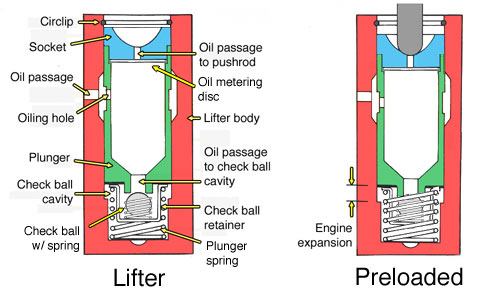
A HYDRAULIC LIFTER BECOMES SOLID IN OPERATION BECAUSE OF THE TRAPPED INCOMPRESSABLE OIL FROM THE EXIT BLOCKED BY CHECK BALL OPERATION. IT STARTS FROM BASE CIRCLE (REFIL) TO ON RAMP (LIFT).
https://www.youtube.com/watch?v=lorANZ1Tptw
http://www.speednik.com/files/2013/03/5 ... onents.jpg
"We know that the engine expansion rate depends on operating temperature. At normal operating temperature, the valve clearance has changed from the initial gap of 0.006" on a solid lifter engine to a smaller one. We know there is still a gap because we can hear it. How much gap and by what temperature only the engineers really knew. That gap is set to accommodate the ideal expansion and since the engine isn't at the ideal expansion at all time, the adjustment is imperfect especially at startup. The hydraulic valve train is designed to eliminate the gap at all engine temperatures: a more efficient design.
Instead of setting the valve lash to 0.006", the hydraulic adjusting screw makes contact with the valve stem and you turn the screw a couple turns and you're finished. No feeler gauges are required. The engine pumps the lifter full of oil and as the clearances of the engine parts change due to heating expansion, the lifter adjusts automatically. Besides fewer required valve adjustments it means less startup wear on the valve train compared to a solid lifter engine because the engine is adjusted at all temperatures not just when the engine is hot.
The lifter has four main components: the body, socket, plunger and valve mechanism. The body moves with the cam and the plunger/socket moves with the push rod. Riding between the two is the weak plunger spring and a cushion of oil. All of the cavities within the lifter are filled with engine oil.
The lifter gets pressurized by the oil gallery feeding the lifter bore only during the start of motion. The oil pressure is just enough fully engage the valve train but not enough to overcome the stiff valve spring and open the valve in the head: that's the job of the cam pushing on the lifter body.
There is a small valve in each lifter and the one illustrated is a check-ball design. The check-ball is held in place by a tiny spring and the motion of the lifter opens the check-ball cavity because inertia leaves the check ball behind but only for a brief moment.
When the cam pushes the lifter body upward, the plunger is held in place by the tension from the push rod and the valve cavity decreases in size slightly. The check-ball inside the valve is held in place by its support spring and pressure from the oil in the cavity forces the check ball forward which closes off the valve opening to the valve cavity. This traps incompressible oil in the valve cavity, causing the plunger assembly to move with the lifter body which moves the push rod and opens the valve in the head. After this point the lifter effectively becomes a solid lifter."
Copied from
http://www.ratwell.com/technical/Hydrau ... #operation, eliminating any reference to "VW"