Building Fox-Body Header for Factory AC

Stormin' Norman

Well-known member
Departed Member
I'm having to build my own 3.3L (200 CID) header, because I like long trips, knowing I can find stock V-Belts anywhere. So an Aussie friend donated flanges and collectors, and sent them to me. Single exhaust, 2 tri-y collectors into a 2 in one collector.

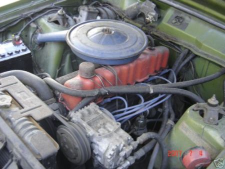
Now to make it really challenging, My motor is out of the car, because I'm repairing the driver's side fender core, but I'm using the head off another 1978 Zephyr donor car that I bought for the body parts and the spare I6. I'll use that engine to build up a tri-power, mild cammed 140 HP machine for regular driving.

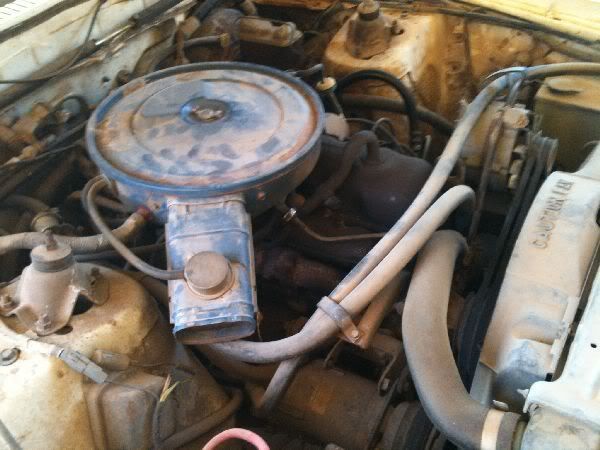
Its too cold to work in my plastic car shelter until early April, up here, north of North Dakota, so I brought the head in and 'mapped out' the header issues and obstacles via dimensions and key locations, like the AC bracket, the K-member, starter, and of course, the exhaust ports. Then I used metal, coloured clothes hanger wire to get some general idea of the angles from the head to the collectors.

Here's the starting progress pics:

I6_200%20HeaderMapWireFrame001.jpg


I6_200%20HeaderMapWireFrame002.jpg


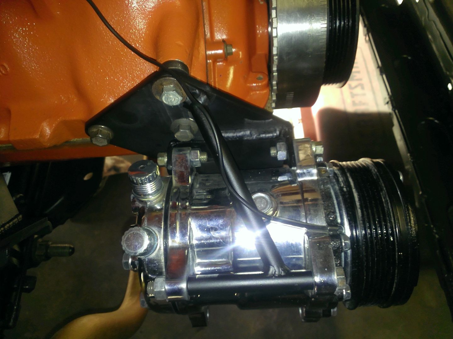
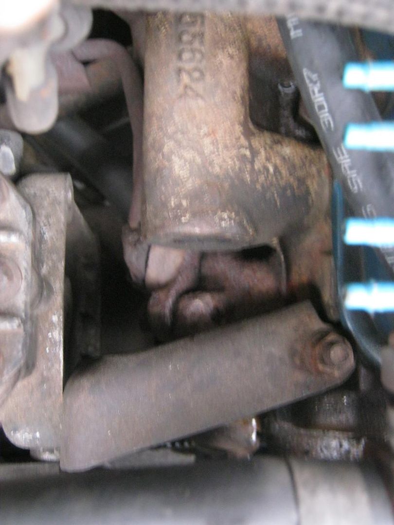
This aqua blue wire shows what I want close to the AC:
I6_200%20HeaderMapWireFrame003.jpg


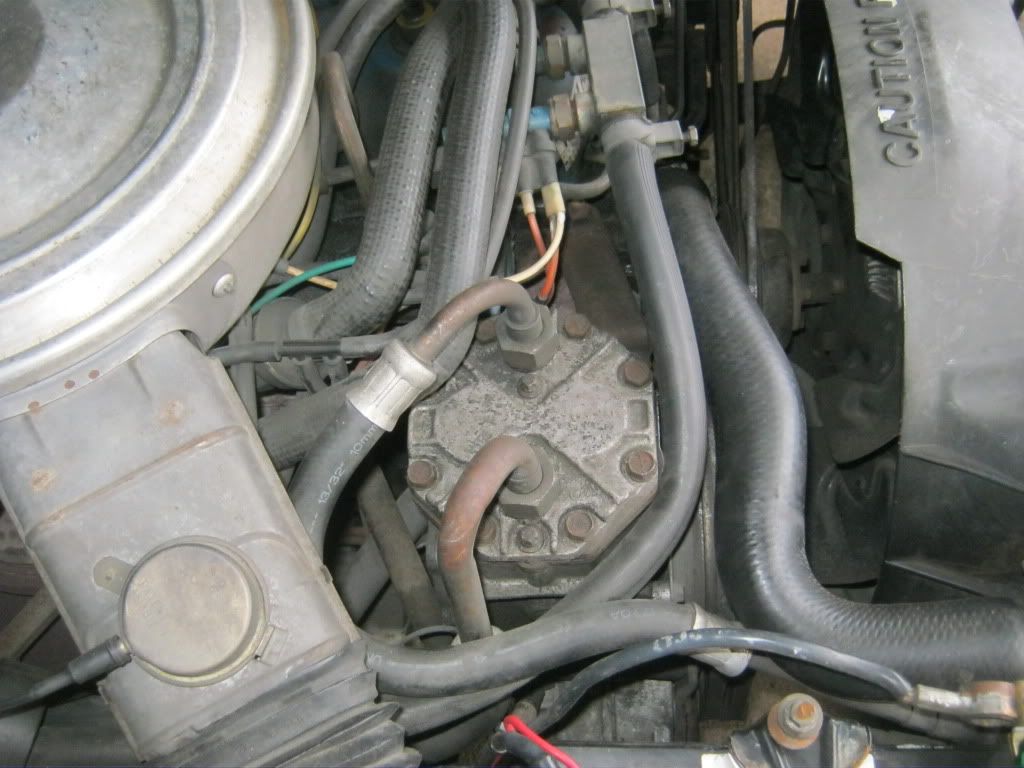
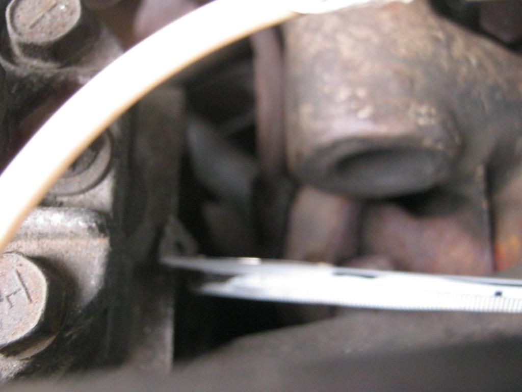
This shows the rough standout distance from the block:
I6_200%20HeaderMapWireFrame004.jpg
 
I'm using 304L Stainless Steel 1/16" wall X 1.5" diameter. I'll take the next Modelling step to PVC pipe that I can bend with my heat gun, then cut the stainless and tack weld it for the mandrel bender, here in town. The shop next to his does Ceramic coating.
 
Good work.

The first non A/C headers were made by Mike for a Classic inlines head.

Our 81Capri did a custom second for his 2v 250 head to 3.3 conversion

See post 09-26-2014, 12:03 AM

http://vb.foureyedpride.com/showthread. ... ang-member


The Fox body has the battery very close, so you can't shift the A/C unit much.Your hemmed in on each side.

You can go to the low mount Sanden/Ogura like our Aussie XE/XF X-flows did and also the later F series 4.9 EFI trucks used, then place the alternator up high like Jack Fishes 3G conversion.

Option 3, the early Aussie and American York A/C units were on the true left

http://vb.foureyedpride.com/showthread. ... ost1613316

xctasy said:
NB//A stock 250 2v head on a stock 3.3 engine takes the stock 67 rear wheel hp up to 105 hp, with 8:1 compression ratio instead of the stock 8.5:1. That's a 57% boost, or stock 92 hp goes up to 144 hp. But with a Holley 350 (similar CFM as the 157 hp 1982 5.0 GT 2V) and the 9.3:1 compression ratio the 1971-1973 250 2V ran, it can go to over 157 hp. A proper breathing head makes a huge difference, its exactly like like comparing a 1967 K code 289 to a 1970 290 hp 302 Boss Mustang, or a 1970 351C 2V 265 HP engine with a 351C 4V HO Phase III or Boss 351C or early Pantera hydraulic cammed GTS 351 330 hp engine. The rear wheel hp difference and general spirit of the 2V 200 engine is the same as comparing the 289 K code and 351C 2V to the hottest Canted valve 302 and 351 Boss small blocks . I know, I've driven behind each engine. They had similar cam spec's, but the better breathing and with 60% greater carburation of the hotter engines, they make the hotter headed Ford engines like the best French women...taken on there own, the head, breathing, aspirations are significant, but added together, these attributes don't just add up, they multiply....


Terry, I am so pleased. It looks soOO clean! It took a while, but everyone is getting into the act you started. Looks like going Aussie performance for the Fox body is the going thing.

Ah the joys of having no emissions inspections for air pump and cat. NAVYCAT, after dealing with all that emission stuff, take note that Terry had to buy your car and take it to Aussie just to get the freedom to do whatcha can't in Cali and several other states!

I only wish Ford US made those 3.3 RS Capris like that from the factory!


That is very awesome. Nice work. Hope things with the health and home are tranquil now

If you want functioning A/C, you can place the old Tecumseh/York/Motorcraft compressor on the drivers side left of the engine bay, where that pesky air pump was. Old XA Falcon's and lots of early dealer installed US Mustangs and Falcon I6's used that set up

XA_six_with_a-c_-4.jpg


(From more on those crazy Aussie engines, see engines2 at http://www.aus-ford-uk.co.uk/html/engines2.html, )


I've got an XA Falcon 200 going in mine, with triple carbs, but it won't ever look as trick as that 2V head.
 
^^^^ Thanks Dean.

I want to get this done so I can send the head out for machining, while I get all the Squire trim polished and ready for the re-assembly, after I paint the car. So it's pedal to the metal for me. If Mother Nature favours me, I'll get a week of warm weather in March to finish welding the body repairs, and strip the rest of the wagon body for primer. Meanwhile I do the already stripped doors, tailgate and hood in the basement to primer grade.

I figure it'll take me to next Friday to get the header ready for the bender shop. They do Aircraft and marine headers as well as handrails.
 
Looking good
What do you plan on doing for a flange when you switch over to stainless?
What size tubing are you running?
Locally (Fargo, ND) there is a company that makes headers
Stainless Headers Mfg., Inc
And while I think they are a bit expensive, they have a lot of nice pictures that give a person ideas on how to make their own headers.
and I asked about the header flange because I've been working with mustang1966 (Perry) to design some new parts, and I have a DXF/DWG for cutting flanges, but haven't cut one yet.
He created them in both 1pc and 2pc flanges and with both 1.5" round and original square(ish) type holes.
smallSixHeaderFlange_rnd.jpg
smallSixHeaderFlange_stk_2pc.jpg
I have not cut any yet, but if you were interested I could get my rear in gear and pop out a couple for test fitting.

I see a lot of Canadian license plates here on the weekends, maybe I could cut you a set and send it back with one of them :rolflmao:
 
CoupeBoy":3ewc9hov said:
Looking good
What do you plan on doing for a flange when you switch over to stainless?
What size tubing are you running?
Locally (Fargo, ND) there is a company that makes headers
Stainless Headers Mfg., Inc
And while I think they are a bit expensive, they have a lot of nice pictures that give a person ideas on how to make their own headers.
and I asked about the header flange because I've been working with mustang1966 (Perry) to design some new parts, and I have a DXF/DWG for cutting flanges, but haven't cut one yet.
He created them in both 1pc and 2pc flanges and with both 1.5" round and original square(ish) type holes.
View attachment 1

I have not cut any yet, but if you were interested I could get my rear in gear and pop out a couple for test fitting.

I see a lot of Canadian license plates here on the weekends, maybe I could cut you a set and send it back with one of them :rolflmao:

The tubing is 1/16" wall 304L SS 1.5" O.D.

I'm going to use these new 3/8" laser cut flanges for now. I love the Fargo, ND site. I've got every one of their HOW-TO videos, as well as others. The 3 flanges I have are strong, and because of their shape, I don't think they'll warp, when being welded. The top bolt 'holes' are slotted to handle expansion, and the bottom mounting holes are really slots to allow for slipping the header onto the bolts. I'll post a picture of them over the weekend.
 
More progress on the Header modelling. I went and got more of those 45 degree joints, but only to fit inside the PVC tubes, not outside. Whatever I don't use, I can return.

Since the exhaust ports are square, and the end elbows are round, I set up my table saw with a 60 tooth blade and squared them off to fit. If they were a bit sloppy, I stuck some electrical tape to tighten them up.

I had some cardboard mailing tubes (1-3/8" and 1.5") and cut them to fit in the other exhaust ports to get a sightline to the collectors.

Now maybe its my linear brain, but I like this looks a lot better than the wet noodle pipes:

I6_Header_Model1.jpg


I6_Header_Model2.jpg


I6_Header_Model3.jpg


I6_Header_Model4.jpg


The PVC tube cuts nice and clean on the table saw, and I do have a metal cutting blade for it too, but I'll likely tune up my bandsaw to cut the stainless tube, and my Makita belt grinder, in a jig I made to use it as a beltsander to cleanup any rough cuts or set the angles more precisely.

Unless there's some mysterious reason why not, as I've got this laid out, the end pipes will pass behind the others, closer to the block, but still 5" away as they travel downward. The rear pipes have to travel forward anyway to clear the starter length (so I can repair or replace it), and that will allow a good size curve, back into the top TRI-Y collector.

Any comments are welcome...
 
Looks great, the pipes really give a better feel for the overall shape that the header will have when you are done.
The wires never really did it for me, and I thought it was because I was spatially challenged.
 
CoupeBoy":25fj9pyi said:
Looks great, the pipes really give a better feel for the overall shape that the header will have when you are done.
The wires never really did it for me, and I thought it was because I was spatially challenged.

I am spatially challenged! :nod: :mrgreen:

I did the wires to approximate the bend lengths, and guess-timate the curvature from the block, to stay within a reasonable distance from the AC, the fender well and K-member, and the block/starter. Amazing how the C4 Fill-tube would constrain the space down below, to keep a decent distance away from it. Why do I like a stick-shift?

I'll get more done today, I hope.

Got almost all my NOS coil spring insulators on the way. Just missing the top ones for the new front coils, but I'm waiting for California to wake up, and order them (also NOS).

Really been lucky finding suspension parts. The heavy duty rear coils seem to be fading into non-production (Moog 8599), but I found them in Canada, and no shipping charges! RockAuto's prices are far better, but the freight is horrible! $91 USD$ 150% more than the springs! I've saved a bundle from their site, for other bits and pieces, but the springs and shocks and struts were too costly to ship into Canada.
 
1986F150six":35xqa72z said:
Very innovative! Definitely thinking outside of the box! (y)

I sometimes work myself into a box, but I think this will work out nice. I'll get some SS rods to weld to the top of the center tubes to mount the heat shield, and use SS wing nuts to hold it place. At least, that's the plan. :beer:
 
I thought I had posted the pics of the 'heat shield' and my original engine bay. CRS hits anybody over 40 - Can't Remember S anything!

The heat shield is just an aluminum perforated step. Air can still move around and cool things off. Handy for tuning 3 carbs. :mrgreen:
I6_Heatshield1.jpg


I meant to post this pic to show how much space there is for the collectors. The C4 fill tube will be gone, so there's lots of wiggle room.

FairmontEngineBay1.jpg
 
I do a lot of widgets and jigs for my various hobbies and tasks on the house, our custom-built furniture and special kitchen hardware and gadgets, as well as my shop and car. That makes me a qualified packrat. :nod:

Anyway, I didn't want to experiment with my 1.5" stainless tubes, and looked up in between the basement joists, for some metal tubing and I found a floor lamp post tube exactly the same as the stainless tube. AND I found another cardboard mail tube that slipped over it like a snug glove. I know the No 1 and No 6 ports are the challengers in this project. No 1 because I don't want to move the stock AC, and No 6 because it has to leave enough space from the above the starter, and curve back into the collectors.

So the question I was tinkering with is how can I make a segmented 90 degree port exit? Then I found a couple youtube flics to mark and fabricate tubing and light gauge channel, even a couple on making tube bender components from wooden parts. Also found one on a product made from magnetic plastic sheet called Wrap-It. Only that won't stick to non-magnetic stainless. So I cranked up my table saw, after making sure it was square to the blade and the mitre gauge was accurate, to cut the cardboard mail tube at different angles. Then I marked off a section of the lamp tube to cut on my band saw tomorrow.

Nice straight-on view of a 200 Cylinder head!
I6_200_Head%20Profile1.jpg


My humble bandsaw (It was made by Ryobi for Craftsman) needs a few tweaks after I change the blade.
I6_HeaderTubeWraps3.jpg


Also found a nice clear picture of 200 I6 with the same AC unit, and estimated the space at 7/8" between the intake manifold and the AC compressor. Don't know if it came from a FordSix member, I got it from an Image Search via BING.COM.
1966_200CID_AC1.jpg


That allowed me to clamp a chunk of 3/4" wood and see if my plastic piece could come out from the bloc a bit more and still leave room to let incoming fresh air run in between to keep the AC in good shape:
I6_HeaderTubeWraps1.jpg


This is the marked up lamp tube, and my assortment of tube marking 'tubelates'. I did one for 30, 45, 22.5, 11.25, and 5.625 degrees.
I6_HeaderTubeWraps2.jpg


Once I test this tomorrow, for bending angles, I'll tack it together, and form it into the flange to see how much it distorts (round plug into square hole).

Here's the youtube links I'm using to guide this experiment:

Tube Bender With Hardwood Wooden - Wood Die
https://www.youtube.com/watch?v=bktdn-ZFIvg

How to fabricate a swept 90 degree bend in cable tray - YouTube
https://www.youtube.com/watch?v=CEy-Wue-gPc

Wrap-It-Cut Magnetic Welding Templates
https://www.youtube.com/watch?v=uQ5efBsjY5Q

How to Seamlessly Join Two Pieces of Pipe
https://www.youtube.com/watch?v=sTdVq8x0l58

I used the 11.25 degree template to draw on the steel tube. I had to reverse it to mark the opposite cut. So each notch is a 22.5 degree cutout, making 4 gradual bends to add up to 90 degrees. I may have to do it over with the 5.625 template to make the notches only 11.25 degrees, if it doesn't make for a smooth enough curve.

I'm an engineer, so Form, Fit and Function are more critical than curvaceous grace. :eek: My wife takes care of that addiction. :LOL:
 
Some other photos fyi. Ford did a massive amount of engineering work to integrate the A/C, and ended up copying the 1965 factory air with the Foxes.

Samrt move, I think.

I personally love the big 4-1/2" cast iron monstrosity header Ford made for 1981 to 1983. Since the Fox battery allows no space for anything except a custom header if your not going to go to a repositioned A/C pump, its my only option.


Options aside from reworking the header are
Left Hand A/C,
low mount GM Harrison Frigidaire A6
or even lower mount Sanden.


The alternatives are major, and it makes a custom header a great first option!

( viewtopic.php?f=1&t=67303&p=515209#p515209 )

First was York/Tecumseh upright (later branded as Motorcraft)
Later Right Hand Side
00q0q_6OFMhNQfLpk_600x450.jpg

http://static1.squarespace.com/static/5 ... 00x450.jpg
IMG_5634.JPG

http://1.bp.blogspot.com/-A4d3nL97RcE/U ... G_5634.JPG
Early Left Hand side

DSCI0645.JPG

http://www.pilgrimage.us/mustangshow/DSCI0645.JPG
XA_six_with_a-c_-4.jpg


Repeat of Aussie Falcon 250 log head A/C which was the same as US early 200

Second was the GM Harrison Frigidaire A6. They swapped the alternator and air pump positions in 1978 on the Granada, but it stayed 200 style like on this 1977 Monarch.
Frames 6 of 12 and 7 of 12, showing Hidden Low mount 1977 250 with early low mount compressor
images

http://www.thetruthaboutcars.com/2014/0 ... met-sedan/
The 78 Granda with GM A6 A/C


Third option,

are Sanden 503/507/508 or SD5H14 retro fit for the York/Tecumseh, which is even lower than the GM Harrison Frigidaire A6 and found standard in later Australian Ford Falcons/Fairmonts/Fairlanes/LTD's from 1985 onwards, and Utility pickups till to about 1992


My Falcon engine has one like ZC Cruiser's

Mike1157 made significant progress on Serpentine version, aka Jeep 258, for our 200.


Images have dropped off the web, but York/Tecumseh upright (later branded as Motorcraft)


viewtopic.php?f=7&t=67132
 
Stormin' Norman":31emiuhh said:
Also found a nice clear picture of 200 I6 with the same AC unit, and estimated the space at 7/8" between the intake manifold and the AC compressor. Don't know if it came from a FordSix member, I got it from an Image Search via BING.COM.
1966_200CID_AC1.jpg


That allowed me to clamp a chunk of 3/4" wood and see if my plastic piece could come out from the bloc a bit more and still leave room to let incoming fresh air run in between to keep the AC in good shape:
I6_HeaderTubeWraps1.jpg


I got 1.1" with my earlier small log. Thats 28 mm in French.


7/8" sounds right for the big Dog Turd.
 
^^^^ Yeah I think there's some wiggle-room on the AC. I figured it was 7/8", without modifying the mounting holes on the AC. Also noticed that the angular brace back to the front of the block has a short 'slot' opening to adjust the bracket, maybe 3/16" inch movement.

I'm shooting for a 3/8" to 1/2" clear space at that one exhaust port. The only other 'tight one' is Number 6. with only about 5/8" to 3/4" above the starter, and enough room to pull it forward when it has to be replaced, but that gets handled when I curve it backward into the collector.
 
Back
Top