Small Six Motor Mount Dimensions

Alrighty folks, another 12 months have passed and I still haven't used a set of these.. I did send off a set to a guy, but hasn't needed them yet either..
Luckily I had a small fire under my took-us created by these guys,

https://www.fordsix.com/threads/worries-about-hitting-carb-touching-shock-tower.72974/ - fixed link

So after a lot of other life delays, I finally got 2 full sets created, finished, and painted.
And here are some build pics.

Cut some new plates
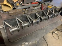
The other brackets in this picture which are NOT small six motor mount brackets are as follows from left to right
Small Six Engine lift bracket (bolts to rear passenger side of some heads that have throttle linkage pads)
The BIG bracket is a Ford 240/300 lift bracket that bolts onto the intake/exhaust bolts.
The small one on the top right is a single hole lift bracket, originally designed to be used on a Ford 240/300, but I suppose it could be used anywhere..
Then the bottom brackets are the ones to be used in building small six motor mounts.

For those that don't know, plasma cutting leaves a little 'blow out' or slag on the bottom side when its done. These plates are fresh from the CNC table, no grinding has been done on them yet.
Small bracket
Front Side

Back Side
(bolts to frame bracket)

Big Bracket
(bolts to engine)
Front

Back

This time I was lucky enough that the CNC Brake press operator at work bent the big brackets for me

For the small brackets, I was not so fortunate, so I used my home made press brake jig

This is the backside of the small bracket after the plasma slag has been ground off

The downside to the small bracket is that I had the large holes cut to be almost exactly the same diameter as the tubing that I want to put through the hole.
In every case I have had to use some sort of die grinder to open up the hole after I had bent he bracket. This is mostly because the hole edge closest to the bend is deformed slightly during the bending process.
 
Last edited by a moderator:
Some of you may recall that I bought one of the cheap spark boxes from Harbor Freight recently, I did a write up on it.
HF 90Amp Flux Core MIG review -- FordSix Forum
That is what I used to do the welding.
My coworkers say that we have some spray here at work that I should start using to prevent splatter balls (BBs) from sticking to the metal in unwanted areas, I really should try it one of these days.
Not the greatest weld, I fixed the gaps later before grinding

It got toasty warm, it was hard to grab the camera and take the picture so fast, so the image is blury :unsure:

I ground that flat and used a grinding stone to remove most of the welding slag from the center hole

Repeat the same process for the other side and then I ended up with this


I applied some Valspar Black primer/paint to the whole thing and got this


And then repeated the process 3 more times (to make 2 complete sets)
Here are the components in various states of building.
Raw flat plates on the right, followed by bent unfinished plates in the middle, along with a section of the tubing used to hold the bushing, and a 3.5" long 7/16" OD piece of tubing that is used as a spacer in the center of the bushing. The rubber bushings are standard/stock 1968 Mustang bushings, I assume they are the same for all Mustangs that use 2.5" wide leaf springs. And then on the far left are (almost) enough brackets to make 2 full sets of motor mounts. I say almost because the 4th and final small bracket was still hanging up after getting painted.
 
And viola! A fully assembled small six motor mount. In this picture the bolt hole being used is the one that would be used if you swapped in a 250, or wanted to lower your 144/170/200 an inch.

 
I rember putting a 250 in my 70 mustang orig engine was a 200. Only motor mounts I could find at the time were like for a 170 in a falcon or mustang. They sat too far rearward in the frame to allign up with the block. Solution was moving the engine back like a inch and a half give or take. Just shortened the drive shaft the amount then cut the ends off the trany mount and welded the left side on the right and viseversa for the left. All worked fine.
 
Nobody makes replacement motor mounts for the '69 or 70 cars with 250's
But if they did, they would exactly like this set that my father in law pulled out of his '69 Mustang when he "upgraded" from a 250/3.03 to a 289/4spd (yes I am still annoyed at him, but at least I got the mounts)

250 mounts are the front set


'69 250 mounts on the top, an Oz 250 mount on the bottom (slightly grey/greenish)


Just look at how much more 'beef' there is in that 250 mount compared to this stock 200 frame/motor mount


I measured the setback once, I'll see if I can find the thread. If I can't find the thread, I'll re-measure them tonight.
Take a gander at this thread
250 Motor Mounts -- FordSix Forum
Forum Member "Econoline" posted the following picture, and you can see that the frame bracket hold down bolt is at least 1" rearward from the engine block mount bolts. Which would be pretty much what you said you had problems with.
Econoline":3rg9zeo6 said:
Here are the 1970 Mustang 250 motor mounts I have.
9gy7.jpg

yaav.jpg

Now my assumption (when I find my original measurements or when I get home) is that the stock 250 frame side brackets already have this difference built into them. So that when the motor is installed the bellhousing is virtually in the same location as a 200 or even a SBF. But when you were mixing and matching a stock 170/200 mount the offset worked against you.

Now if that is the case, you could still use the mounts I made, but you'd want to drill a second set of holes in them.
The big bracket that bolts to the engine has enough material that you could easily drill a hole 1" forward or rearward of the original/center mount holes.

Measurements for the 250 mounts are on this thread from eons ago (circa 2005)
Fitting the 250
coupeboy":3rg9zeo6 said:
I need to get some more pics to help with this description.
Frame and Motor mount comparison
Parts compared
'67 Mustang
C7ZA-6037-A (frame mount)
C7ZA-6038-C (Blue*)
C7ZA-6038-H (Green)

'69 Mustang
C9ZA-6037-B (frame mount)
C9OA-6038-D (mount)
C9OZ-6038-B (also on mount)

Setup
I used a peice of 2 by 2 angle iron for the measuring jig. I started by drilling the lowest hole into the angle iron. I then put a bolt through the hole with the nut left lose so I could swing the assembly. I used the '67 frame and motor mount for the next step. I put a level along the motor side of the motor mount and when it was straight up and down I clamped it with a big pair of pliers and ran a drill down the hole that would be the farthest from the motor to mark the location. I then took the frame mount off the jig and drilled out the hole. After the holes were drilled I bolted teh frame mount to the jig and started measuring.

From the end of the jig to the horizontal motor mount face
'67 9.5
'69 9

With the motor mounts oriented as they would be while holding the motor
From the table to the center of the lowest motor bolt
'67 3 5/16
'69 3

I then tipped the jig over on its side and measured from the counter up to the center of the bolt hole that is closest to the jig.
'67 5 1/4
'69 4 3/4


So according to what I found, the '69 frame and motor mounts should lower the motor 5/16" lower, and they make and adjustment to allow for the wider block. The part that was interesting is the 1/2" setback. I noticed that the '69 frame mounts have oblonged holes in them for additional adjustments. I still need to make measurements for the bolt spacing where it bolts to the frame. You also have to allow for some slight miscalculation of measureing as I did it with a tape measure.
 
Down and to the rear as far as possible both ways.. that's what I'd like to do..
On another forum I read, I guy built his own custom brace for under the engine of his Mustang so he could lower the motor until it almost touched the steering components. He didn't do it specifically for handling, rather the large manual transmission he put in ate the entire transmission tunnel and he needed to get the engine low to maintain a decent angle on the driveline.

Now if I could come up with a way of allowing the engine and transmission to be mated and in the car and then slid back until it almost touches the firewall, that could be interesting.. then theoretically I could tighten all bellhousing bolts before shoving it back. I wouldn't have to worry about space to turn a wrench..

I've been thinking about it because for my '67 Mustang I'd like to install a 300, the installation should be similar to this one by NitrousNick
(somebody really should make this a sticky -- hint hint) https://www.fordsix.com/threads/how-to-install-a-300-in-a-mustang-falcon.56067/
 
Last edited by a moderator:
8 years later, and I'm finally able to 100% fabricate these at home.
I sold 3 sets early last week; and 2 more pairs this weekend.
If you need a set let me know.
3Setsi6MotorMounts.jpg3Setsi6MotorMounts.jpg
 

404 Not Found​


nginx/1.14.0 (Ubuntu)
as bounce back on f6's "how to puta 300 ina stang".

I'm forgetting now...what is the bolt spacing ona 300 anyway?:
2 horizontal / 1/2 apart / 5 8th inch by 1 inch deep / NCT 8, 20
 

404 Not Found​


nginx/1.14.0 (Ubuntu)
as bounce back on f6's "how to puta 300 ina stang".

I'm forgetting now...what is the bolt spacing ona 300 anyway?:
2 horizontal / 1/2 apart / 5 8th inch by 1 inch deep / NCT 8, 20
Fixed link in original post.
 
"...Fixed link in original post...."
yup, thank U Perry.
Is this an easier platform on ur end of things (wrker bee, not us consumers)?
 
@chad - Yes, much easier - but these link redirects - some are handled properly, some are not - I just need to fix how the server handles certain old links when I have a minute.
 
Back
Top