Modifying the Holley HyperSpark distributor 565-315 (made for the "small block") to work with a "big block" Ford 240 six or 300 six (with Holley ECMs)

I am reading this as, the module serving as a passive interface. It will have no duty as an ignition control module anymore?
Yes, as far as I can tell, the PIP signal from the module is a pass-through of the hall-effect sensor. So the largest function of the module is to close the big hole in the side of the distributor. Also, as far as I can tell, the hall-effect sensor in the Holley and the Ford are identical - at least the molded plastic is identical.

So it appears that Holley basically copied Ford's vane and sensor design (not that there is anything wrong with that).

Yes it will be a passive interface and the Sniper 1100 takes on the ignition timing duty.
It can still be used as a TFI ignition coil driver but then you are back to the heat issue that caused Ford to move the unit remote from the distributor.

Ah, that explains why the module has a big aluminum plate as its back, which mates with thermal paste to the distributor housing. I put it back the same way with some thermal paste I had on hand. I do not know what they were thinking, trying to cool electronics by thermally coupling them to a hot motor :rolleyes:. Well, maybe I have a hint . . . the whole thing looks like someone trying to incrementally push advanced electronics into a then 40-year-old mechanical design against huge institutional resistance to change. Good for me in this case :)

I did not mention above, but I used some high temp RTV to secure the black plastic hall-effect sensor assembly to the shaft so it is completely immobilized. The Ford design has an arm to lock it in place, but it still could wiggle slightly. Not anymore.

I will say that the Ford distributor has amazing mechanical design. Oil passages inside the shaft, even a special washer with an oil passage. There is a spiral track on the outside of the shaft to manage oil distribution, pure end-stage mechanical design evolution.

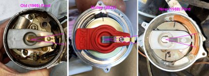
Another -- possibly minor -- thing about the Ford design is that the rotor has a wide arc at its tip. This design should allow the rotor to be close to the points in the cap for a longer period, allowing more freedom for the ECU to change the spark timing. The Holley rotor has a narrow tip.

I will be away from testing this distributor for a bit, I need to make a throttle cable, get the throttle body mounted, finish the fuel lines, and do all the wiring. Plus I'll be away for a few days so it may be a while before I update. I'll post progress on all that other stuff over on the My 1969 F100 Big Block Six 240 Holley Sniper EFI Train Wreck Project thread.
 
Last edited:
I believe that the distributor is supplied power from some other component in the Holley system.
The distributor gets its power from the ignition adapter cable that is supplied with it and not from some other component in the Holley system.
The cable has a two and a three pin connector with a pink wire that goes to a switched power source controlled by the ignition switch.
The Holley Sniper gets its power from the same point.
The two wire connector only supplies trigger signal form the Hyper distributor to the Sniper.

The Sniper triggers on the signal edge that goes from zero to supply voltage the same as a set of points would do.
If the two wires were reversed the Sniper would trigger on the other edge and the ignition timing would be off for one of the six cylinders due to the cylinder #1 ID spacing.
The rotor phasing will be off also.
If you make up a new cable for the Ford distributor make sure the polarity it correct.

Once the engine is running I would check the trimming on all six cylinders just to be sure.
Once the distributor timed with a timing light you will need to check the rotor phasing.
 
I did not mention above, but I used some high temp RTV to secure the black plastic hall-effect sensor assembly to the shaft so it is completely immobilized. The Ford design has an arm to lock it in place, but it still could wiggle slightly. Not anymore

Another -- possibly minor -- thing about the Ford design is that the rotor has a wide arc at its tip. This design should allow the rotor to be close to the points in the cap for a longer period, allowing more freedom for the ECU to change the spark timing. The Holley rotor has a narrow tip.
Glad you were able to secure the sensor to the housing. On the earlier pics of the distributor, the rubber exterior cover under the single-screw hold down was gapped at the bottom, and you had wiggle. My (untouched) factory distributor, the sensor plated is immovable, and the rubber cover is flush to the housing on all sides. Shouldn't wiggle, someone else didn't reassemble it carefully. Good catch.

I am surprised the Holley has a narrow rotor contact area, considering all timing advance is dependent on that contact patch.
 
Please explain.
The relationship rotor-to-cap is fixed, locked in place on the computer timing units, unlike cent. advance where the rotor moves forward relative to the dist shaft and cap as the timing advances.
A wide rotor contact end at the cap post is necessary, since as timing advances, the rotor is still arriving at the cap post at the same time as base timing. If there's not enough leading edge on the rotor end, the advanced timing spark won't transfer to the cap.
 
Great information.

One more favor please for the sake of adding to the information base.
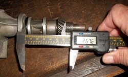
What is the measurement from the bottom of the distributor hold down collar to the bottom of the gear on the 88 distributor?
Thanks

I just added this thread to the information stickies in the "240-300 Big Block Six Performance" section
 
Last edited:
. . . What is the measurement from the bottom of the distributor hold down collar to the bottom of the gear on the 88 distributor? . . .

Ummmm . . . I'll have to pull it out and then do the static timing again. Give me a bit.

. . . I just added this thread to the information stickies in the "240-300 Big Block Six Performance" section

That might be a bit premature . . . I do not know that any of this works at this point :-(
 
The Holley has that same arrangement - one vane is more narrow. I'll get some more photos and measurements tomorrow.

One thing I do not like about the Ford distributor is that the mechanism that could be used for mechanical advance (but is locked out) makes the mounting of the hall effect sensor a little wobbly compared to the Holley which is rock solid.

I'll poke around tomorrow and formulate a plan. I'll probably end up with three distributors, none of which work.
Looking at the hall effect sensors of the Holley and the Ford:

View attachment 11020

Except for the connections, the sensors are identical. Also, I verified that the Holley uses a hall effect sensor.

I got the Ford distributor completely disassembled, cleaned, lubed and reassembled:

View attachment 11021

I got it installed, and did static timing of 12° (from @djstucker's video, IIRC) on what I think is the correct vane inside the distributor. I guess I'll see if it was correct.

As far as the diode, I will have to see how the Holley wiring goes - - I believe that the distributor is supplied power from some other component in the Holley system.
DO YOU HAVE MORE INFORMATION ON HOW THIS WORKED WITH THE SNIPER
 
DO YOU HAVE MORE INFORMATION ON HOW THIS WORKED WITH THE SNIPER
 
  • Like
Reactions: Ktn
I'll have a big writeup later but me and my dad also have a 240 with a Sniper and a 90s remote-TFI distributor running successfully with computer timing.

We were not able to get the truck to run with the distributor as it came. When the distributor was put in time, and the reference angle set to 57.5 to match the Hyperspark distributor reference angle, the rotor ended up being pointed almost exactly between two posts on the cap when it fires (10-15 BTDC at idle or start), making it unusable with that reference angle setting.

By my measurements, the physical reference angle of our 90s remote-TFI 'F2TE' distributor is about 35 degrees BTDC, which when the distributor is timed leaves the rotor pointing directly at a cap post at 25-ish BTDC, right where we want it.
Holley software expects the reference angle to be greater than the maximum advance you want to have, plus 10 degrees of margin, so the 'correct' reference angle of 35 is not useful. Using an angle of 155 (1 trigger tooth later) might have been an option but I didn't think that the Holley EFI software would accept a reference angle that high as it would cause overlapping delay events.

We did figure out how to advance the hall effect pickup about 10 degrees on the distributor (20 degrees at the crank) to get the reference angle to be usable.

Under the trigger wheel there is a little flat metal bar link securing the rotatable black magnetic sensor frame to the distributor housing.
The sensor frame has another post for this link 90 degrees counterclockwise from the one it comes attached to.
By switching the link over to that other post the sensor is advanced by 20 crank degrees, which puts the reference angle at 55 which is perfect for getting usable spark advance range. After setting that angle in the Sniper and timing the distributor again the truck fired right up.

Baxsie, I am curious how your setup seems to work without needing to phase the rotor like we did (by advancing the sensor). I wonder if there is a difference in the sensor reference angle between the TFI-module-on-housing distributor vs the later Remote-TFI distributors?
 
Last edited:
. . . Baxsie, I am curious how your setup seems to work without needing to phase the rotor like we did (by advancing the sensor). I wonder if there is a difference in the sensor reference angle between the TFI-module-on-housing distributor vs the later Remote-TFI distributors?

This has been a while, and I had to re-read all of this thread to remember what was going on. I do not remember trying to push the sensor one way or the other to change the rotor angle compared to the hall effect sensor position.

Do you have one of the wide contact area rotors from this post?

In this post, I mentioned that I glued the plate down in addition to using the link that keeps the plate from rotating.

Keep in mind that I am using the Holley Magna Spark, which will jump about a mile-and-a-half so that could be covering up any rotor misalignment in my case.

If you are sure you need to adjust the phase between the rotor position and the hall-effect position, you could always make a longer rod or drill a shorter hole in the rod that fixes the plate that holds the hall-effect sensor. That mechanism is left over from the old "vacuum advance" days. It seems like that would be a fine place to change the phasing.

I do not remember any Holley information or any internet stuff being useful to get the initial timing correct.. IIRC, I messed around with the timing light, distributor rotation and the wire arrangement until I got the cranking spark to about the correct place. Once all that was actually working (I think it was idling on its own by then) I followed Holley's instructions to set the reference timing using the timing light.

At that point, the ignition seemed solid and I have not touched it since.

Do you guys have experience getting a good tune? I'm happy to send you mine, but I do not think it is very correct. The big problems I have are that it is less luggable than the carb -- giving lots of throttle at 1500~2000 RPM makes it stumble. And it has Russian roulette starting. Most of the time it starts OK. But sometimes it will flood, which requires a clearing crank (pedal at 100% so PW is 0) and then another try to start. So far it has not stranded me.

Best of luck. If you get a good tune, lets share.
 
At that point, the ignition seemed solid and I have not touched it since.

Do you guys have experience getting a good tune? I'm happy to send you mine, but I do not think it is very correct. The big problems I have are that it is less luggable than the carb -- giving lots of throttle at 1500~2000 RPM makes it stumble. And it has Russian roulette starting. Most of the time it starts OK. But sometimes it will flood, which requires a clearing crank (pedal at 100% so PW is 0) and then another try to start. So far it has not stranded me.
Appreciate the update Baxsie, it's been a minute. And glad to hear it's still firing on the old TFI distributor. . Give a little more info, I'm thinking about this low vacuum stumble at 1500-2000.
What Holley injection do you have?
Intake manifold? If it's TBI injection, does the intake have heat?
Carb or EFI head?
This is a 240 engine?
 
Do you have one of the wide contact area rotors from this post?
Mine looks like the one in the rightmost photo.

giving lots of throttle at 1500~2000 RPM makes it stumble. And it has Russian roulette starting.
Maybe you could pull the cap off and see where your rotor is pointing when your engine is between 10 BTDC to 40 BTDC. Ideally some part of the rotor blade should be in front of the post throughout that entire range. If the spark has to jump very far it could be causing your stumble. I phased ours so that the rotor points directly at a post when the engine is around 25 BTDC, and even at 6 BTDC the right half of the wide rotor blade is still in front of the post.

Adjusting the reference angle in the Holley HyperSpark settings suffices to phase the rotor, the only issue is you have to reduce the reference angle quite a lot to move the rotor a meaningful distance. 2 degrees of reference angle reduction (crank angle) advances the rotor position (and timing) by 1 degree (distributor angle). So you will also have to turn the distributor housing to put the firing back in time after changing the reference angle in the Sniper.

The amount of reference angle setting reduction needed to phase the rotor back towards a post was in my case way too great and limited maximum possible advance, that's why we phased the sensor instead.

Note that for a given spark advance timing, turning the distributor alone will never adjust the rotor phasing, because for a given timing the rotor will always fire the same distance after passing the sensor. The reference angle setting is what manipulates that distance.
 
Last edited:
@Frank: I have the Holley Autolite 1100 kit. Intake is dumb old log style. Intake and exhaust meet and there is some kind of mechanical valve that is not stuck. Dumb old carb head. Yes a 240.

Properly, I should have posted on the main EFI thread (this thread is only for the distributor):

 
I see some good theory in-application here for rotor phasing(y), but you can calculate the crank angle where the rotor should be exactly aligned at the cap terminal. This ensures the rotor is as close to centered on the terminal at any advance, reducing spark gap and potential cross-fire. I created this 'formula' to find optimal alignment angle, using base timing and max advance. It makes the job clear and quick. An excerpt from an article I wrote a few years ago:
PSIG said:
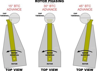
Abstract difference in theory:Rotor phasing with mechanical-advance distributors was traditionally just making sure the rotor was generally aimed at the center of the correct cap terminal when it sparked. With mechanical advance, the rotor phasing and alignment was automatically maintained, as the rotor is rotated internally (separate from the distributor shaft) by the advance mechanism during advance change. But if the mechanical advance is locked or removed to instead change timing with external control (e.g., electronic timing control), the rotor moves alignment to the cap terminal with advance change, so we just place the rotor at the center the range of travel, and we're good. Here is a diagram I made some years ago to demonstrate this rotor angle change with external ignition timing control:

Rotor phasing - PSIG.jpg

How I do that: So, to find the best average rotor phasing alignment for all general timing conditions, the formula I made is:
Rotor Phase Target Degrees = (Max Timing - Cranking Timing) / 2 + Cranking Timing
An example of this could be an engine that cranks at 10°BTC, WOT timing of 32°, and has a maximum advance (usually under lean part-throttle cruise or deceleration) of perhaps 40°. The two we are interested in are 10° and 40° as the maximum range of rotor movement, where we need to keep the rotor tip as close to the cap terminal as possible at all times. That's a range of 30° (40 - 10) we need to center in, that begins at 10° (cranking). The example calculation would then be:
(40 - 10) / 2 + 10 = 25°BTC
I mark the distributor body where the #1 cap terminal is and remove the cap so I can see rotor alignment to that mark. I tape or clamp a stick or rod to extend the mark if I can't see it well. I set the crank to 25°BTC, and align the rotor with the cap terminal #1 mark or stick, usually by twisting the distributor body. Done. Now I can set the Trigger Angle (trigger point versus TDC) and I'm good for rotor phase and active timing control.
I'll note here that max advance can approach or exceed 50°BTC for many engines, so verify your actual rather than assumed max. Also, that different systems may use different terms for Trigger Angle above. :sneaky:
 
Last edited:
Back
Top