Duraspark with GM Module - couple of quick questions

salty_monk

Well-known member
I am working off of this wiring diag:


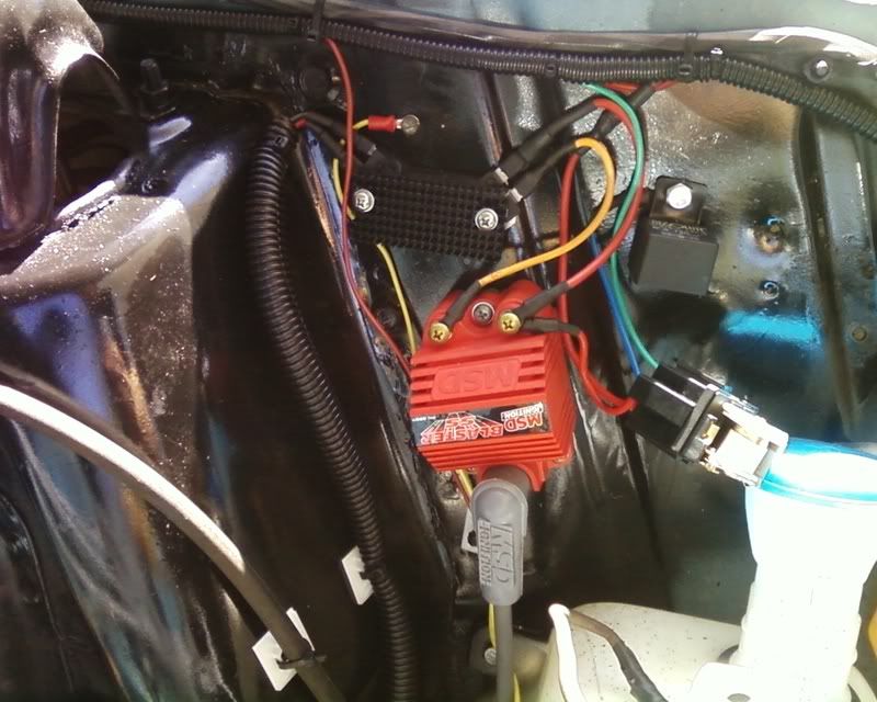
My DSII dizzy has 3 wires, violet, orange & black/white. I assume black/white is just a ground, can anyone confirm?

I have put a fuse in the main feed from the battery, what size fuse is recommended? 20amp?

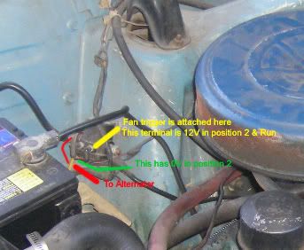
I have a blue/red wire connected up to the current + of the coil that is hot in run, it comes out of the original wiring loom but is not 9v it's 12v. Is the coil wire normally blue/red on these?

Someone has run a new wire to coil - (neg), it goes from dizzy to coil & then follows coil + back to behind the dash, any clues where that would connect behind the dash?

Cheers,

Dan :)
 
The Black wire in the connector is a Ground. It is not completely necessary, but a couple of us with the setup go ahead and attach a spade connector there and a ground connector on the other end at the Module. I was too lazy to replace the wire from the Ballast Resistor, so I just bypassed it with a new wire from the Coil "+" to the same female bullet connector at the back of the Ignition Switch.
P1010034.jpg
GMHEIwithGnd.jpg
 
Most of the Ford wires from the firewall to the ignition are red with a tracer, iirc mine was green.

That wiring diagram is a bit odd. Why add in that relay, and where's the Ford starter relay (solenoid)? You could easily just run the power feed from the ignition switch straight to the ignition, no need to go through a relay. Ignition doesn't draw that much amperage.

No telling where that previous-owner-added wire leads to, but I'd guess the switched side of the Ignition switch.

Here's a simpler way to wire it up. As a side note, unhook the (brown?) wire from the "S" terminal over on the Ford starter relay, or you can fry wires under your dash (he said knowingly).

HEI.JPG
 
The GM module is a power hog, takes lots of AMPS hence the need for the heat sink & such. Switching all that power through the ignition switch is a recipe for burning out your ignition switch....

What does that wire on the S terminal do & why would it fry things under the dash? (I only have two terminals there, one is live with ignition on, I assume the other is live under position 3 (start) but I haven't put a meter on it to find out. Which one is the S?

I will take a look into that, thanks for pointing it out....

Dan :)
 
ahhh
i think i see the problem, your distributor cap in that picture has way too many posts, no need for those two extra ones
;)
and jaymers is a bit unclear about the S terminal, maybe he means how it's hooked up in his diagram? but that doesn't make much sense to me...
 
:lol: You mean that's not the right way to upgrade to a V8, I thought all I had to do was put that new cap on & pow... 300hp :P :lol:
 
salty_monk":1i4wij3w said:
Someone has run a new wire to coil - (neg), it goes from dizzy to coil & then follows coil + back to behind the dash, any clues where that would connect behind the dash?

Cheers,

Dan :)

it's most likely a tach wire.
 
Good fun. Jamyers is right about removing the brown from the S terminal, he saved me from myself about a month ago. If you don't it back feeds 12v from the wire you bypass the pink wire with to the solenoid. (looking at the diagram 12v through the yellow new wire out to the coil and back feeds through the connector into the brown cranking wire and to the solenoid)
The brown cranking wire was only needed to provide a full 12 volts when cranking then the pink wire brought it down to six, you won't need it any more.
When your checking the current to your + terminal on the coil is the engine running, keep in mind the pink resistor wire only resists under a load. So if the engine isn't running you'll get 12 volts, I did.
Looking at my Crummy diagram I cut out the pink resistor wire on my 67 stang. I pulled 12 volts off a second green and brown wire coming from the run position post. and ran it to the wire going to the coil.
To simplify you can run a new 12v wire from the "run" position on the ignition directly to the + post on the coil. This should provide 12 volts while cranking and running. But.... I have been wrong before.

I'm also a little confused about the relay. Your only running 12v through the ignitin switch, which happens with or with out a relay in place. Why would that burn it up?

WireDiagram.jpg
[/img]
 
New Extra wire... tach wire... why didn't I think of that! (Probably because there is no tach fitted & no hint to one ever having been fitted). Thanks I reckon you're right! :)

It's nothing to do with the voltage on the module, it's all to do with the amps... High load on the ignition switch will cause increased wear on the switch & I also don't believe the stock wiring to the ignition switch is safe for running that module. I read a piece where somebody monitored it's current draw & it's a lot! I can't remember offhand the exact figure but I think it was around 10amps. Fitting a relay can't hurt in any case.

Thanks for the diag & the explanation. So I can be sure I have it right when is the S wire live?
I have my radiator fan triggered (main power comes from relay) off of one of those terminals that is only live in ignition on position. I'm presuming the other one is the one that is appears to be dead but probably runs 12V when the ignition switch is in crank position??

Does this help? (click for bigger pic)


If you don't bypass the resistor wire but "Tap into it" right before where the resistance starts as a lot of the instruction state then presumably you don't get this issue? Is it only because you are now using the green wire?

Dan :)
 
Making sure I got it all right I would test the voltage on the S post with the ignition in the run position. You shouldn't be getting 12v to the post. But you should get 12v back feed from the resistor wire in the brown wire. Try removing the brown wire off the S terminal and testing the wire itself and the post separately while in the run position. If I’m correct you'll get a voltage reading from the brown wire and NOT the post. The brown wire just bypasses the resistor wire during cranking. So when you're in the start position you send 12v to the solenoid which closes it sending power to the S terminal and starter.

I thought about splicing into the resistor wire, but after cutting into it and seeing the four or strands of wire it has if decided against it. I’ve heard of some guys saying the resistor wire doesn't start till latter down the line, if that’s the case I would run off the wire that feeds the resistor. The green wire I spliced into comes from the same ignition post and has a full 12v. Where I spliced it back in at mimics the stock set up, which isn't absolutely necessary because it causes the 12v back feed through the brown wire. You may want to keep this back feed if you’re running you fan off of it.
Test the solenoid as I described above and let’s see what you get.
 
Ok, will try to run those tests. Neither of my wires are brown though, must be different colour codes.

I believe it must be the other wire (not the one running the fan) that is the S terminal but I'm not sure.

Testing the feed to my coil (red with a thin green stripe) last night it puts out over 12v even with the engine running so I am guessing the ballast resistor has been removed on mine.

With that said I think I am safe to use that wire without doing anything to the S terminal/wire as I would only be using the exact same configuration that is already there (& don't currently have smoke appearing from under the dash....)

Dan :)
 
Its always possible a PO bypassed the resistor. What distributor did you have before upgrading to the Durspark? Pertronix? But like you said if your getting a 12v to the coil and have been running like that for awhile you should be safe continuing to run like that. Maybe Jaymers can give us a bit more info on exactly what happened to him. Good luck
 
Regarding the "brown" wire on the "S" terminal of the starter relay - I'm referring to the one that's only hot (12V) while the starter is engaged. It's original function was to supply the points with full voltage for starting only (hence the "S-for-start" marking on some solenoids). If you leave it intact you may well have no problems, but if your starter solenoid ever starts acting up (like mine did) you can be "back-feeding" full voltage through the ignition feed wire coming off the start switch. Mine got the feed wire hot enough to burn off 6 inches of insulation. So...it's just cheap insurance to remove anything from that "S" terminal since it's not needed.

On the HEI amperage draw... stock HEI modules generally only draw about 4 amps. Some GM performance modules draw around 5.5 amps. Some high-performance aftermarket modules can draw as much as 8 amps. So unless you're running a high-zoot HEI module (way overkill on our not-high-revving engines), I still don't see the need for a relay and oversize wiring. Mine (basic GM module) has been running fine for about 2 years now with no relay and basic 12-14 gauge wiring. But - a relay hurts nothing, and would make an anti-theft device easier to add on. :D
 
WHOOPS!!! Just realized that I've had my starter relay/solenoid terminals mixed up - "S" instead of "I". The "S" terminal is the one that triggers the solenoid to spin the starter, and the "I" terminal is the one that temporarily feeds full 12V to the ignition.

Sorry for the cornfusion...

Speaking of Ford starter relays, back in the day they were what made it easy to hot-wire a Ford.

Step 1: Connect a short jumper from the battery side to the "I" terminal. This gives you voltage to the ignition - a full 12V, which will eventually burn out the points, but not before a good joy-ride. :twisted:
Step 2: Temporarily connect another short jumper from the battery side to the "S" terminal - this spins the starter. Once the engine fires off, unhook this jumper and away you go.
Step 3: Be aware that nothing controlled by the ignition switch will work, since you've bypassed it completely. No radio, heater, etc.
 
Thanks for the clarification Jamyers, as well as the easy way to boost an old mustang, locking hood pins here i come. I saw that SOB eyeing my girl :shock: Anyways, salty monk, all that fancy electrical testing I had you doing may need to be switched up. In your picture the green points to the terminal that receives 12v from the ignition switch when it’s in the start position, you may want to check that for sure. Which means that the other terminal, yellow indicator in you pic, is 12v switched when the ignition is in the start position. While in run you shouldn’t get any voltage at the ‘yellow’ terminal when the wire is disconnected and you should get 12v or so at the wire disconnected from the I terminal.
 
Thanks for confirmation on amperage... I guess I could have simplified things then, my 12V to coil is currently 18 gauge though so it's prob not a bad thing & a relay never hurts :)

Also thank for confirmation on the I terminal & how to test. I will do some testing & see how we go.

Hope to fire it up tomorrow.

Dan :)
 
So wait could i run things off of the little threaded bolt coming out of the ignition switch? I ask in terms of wiring up relays because that makes it just a circle connector away :).
 
rommaster2":1i1woky4 said:
So wait could i run things off of the little threaded bolt coming out of the ignition switch? I ask in terms of wiring up relays because that makes it just a circle connector away :).
I wouldn't think you could. And if you could, I don't think I would.

To simplify, here are the terminals on the starter relay/solenoid, going from left to right (some are different, but most Ford relays are laid out this way):

1. BIG terminal hooked straight to the battery + side with heavy cable. Always hot (unless the battery is dead..).

2. Little "S" terminal is fed 12V from the key/ignition switch on the dash, it's what triggers the starter relay/solenoid.

3. Little "I" terminal is only hot while cranking the engine, just like the large terminal hooked straight to the starter motor. Some later relays don't have an "I" terminal.

4. BIG terminal hooked straight to the starter motor with heavy cable. This is the main output from the relay, hot while cranking only.

(pic from PartsAMerica's website)
Relay.jpg
 
All wired up, got it started & timing set to 10*Btdc.

Then I came to switch it off... problem... it doesn't switch off on the ignition switch! I pulled the fuse on the relay & off it goes...

So out comes the meter... Anyway, the relay is working fine but by pulling the case on it I can see that it's stilled switched when turning the ignition off, get the meter in the back of it to the "trigger wire" & I can see it's still receiving voltage when the engine is running (maybe a couple less volts or maybe just bad connection.

Any ideas? Here's a pic of the install you can see the relay is open so I could see the contacts. The green is the switching wire. It is connected directly to the wire that used to run the +12v on the old coil supply the point coil. I haven't changed anything there (except lengthened it a little).


I tried Jamyers deal with the Solenoid by first pulling one then the other. The I & S is exactly like his diag above but it doesn't make any difference if I remove the I terminal from the solenoid, same thing happens, it still doesn't stop.

The module is also running very hot (hot enough that the heat sink would sizzle if you licked your finger & applied it to the top after about 10 mins running. That doesn't seem normal to me....

Help!! :?

Thanks,

Dan :)
 
Have to ponder the relay issue...

Regarding the hot module, they'll run warm, but hot enough to scorch yourself isn't good. You *do* have a good layer of heatsink grease (not dielectric) between the module and that sink, yes? I think I'd get a bigger heatsink - or I've heard of folks mounting the module (w/ grease) onto the inner fender, using the fender as the heatsink.
 
Back
Top