Duraspark with GM Module - couple of quick questions

Been reading up on the heat thing, not sure why I need a bigger heatsink (yes there is some of the right stuff on there, transmission through to the heatsink is great) but I have a 2nd one I can sandwich on top of that one with not too much trouble that should sort it out.....

I guess tomorrow I'll check continuity between 87 & the input from the battery to make sure it's not coming from there & try a 2nd relay (I have a spare of the same type & even a couple that are "known good")

Presumably the "noise" from the coil or module in proximity to the relay couldn't be causing this...

On the diag it says to use twin 87 output relays (not 87/87a - 87a is a NC post). I have run from 87 to coil + & then from coil + to the module as a way of getting power to both... can't see that making a difference but I guess you never know....
 
What sort of module are you using, a basic GM replacement or a higher-amp aftermarket one?

Might try it without the relay at all, adding another relay to trigger that relay seems over-complicated (to me, anyways).
 
Aftermarket "Niehoff" unit from Kragen. I don't believe the relay is the issue, the relay is doing what it's meant to do.

I believe I am getting feedback to the relay, possibly through the Gen light wire (as it has an alternator conversion).

I'm going to experiment with this today maybe by removing that wire from the alternator & testing again...

Dan :)
 
Shouldn't be drawing that much amperage, then. hmm.

Gen light feedback? I know MSD units will do that, my Buick ran on until I added the recommended diode. Come to think of it, when I had an MSD box on the Ranchero it didn't run on. Now I wonder why, since they've both got alternators and dummy lights.

Let's see...All of the relay terminals should be 0V with the switch off except for the battery-to-ignition feed at #30.

I'd check for voltage at the switching wire (unhooked from the relay) in this order:
* switch off, engine off (should be 0V)
* switch on, engine off (should be 12V)

Then I'd bypass the relay, temporarily connecting the "hot-inrun" #86 switching wire to the #87 ignition feed wire. Start the engine.
* switch on, engine running (should be 12V)
* switch off, (should be 0V and engine should die)

That'll tell you if (a) the ignition switch is actually cutting voltage to the system or if there's another feed somewhere, and (b) if the relay is the culprit. Somebody mentioned the coil interfering with the relay, and that may well be an issue - coils being electromagnets and all.
 
Sorry to jumpp in but I had a quick question.I installed my duraspark module hooking up the red wire directly to the "I" terminal on the relay.I did this as a quick install.but Havent noticed any problems with this so please inform me whats wrong with this.I thought it was a good idea but confused with this post on it. thanks again
 
With idiot light connection removed from back of alternator it works fine (but no light obviously which would be nice to have).

Works whether the brown wire on I terminal is connected up or not, no problem either way.

So there's the problem, feedback through the Gen light wire. How does this Diode upgrade work? Any "how to's" on it here?

I'm halfway happy now :D

I doubled the heatsink for the module, still hot so I'm now adapting one I have that's over 1/8" thick at the base with fins about 3 inches high. It's about 4 time the size of the module in base surface area too... hopefully that'll stop it getting hot!!

Thanks,

Dan :)
 
Big Heatsink seems to have helped a lot with the module. Can now hold it even when back after a long run.

Fitted a diode in the idiot light line today (1A) worked out great.

Still got my fan relay trigger connected to the brown wire "I" terminal on solenoid as a switched 12v, not too sure what to do about that. Looking at the wiring diagram I think it would be best to disconnect it from the I post & connect it to the fan relay directly. That should give me a switched 12v with no chance of a backfeed from solenoid....

63_wd_07.jpg


Dan :)
 
I'd be leery of using that "I" terminal for anything. What you're really doing is pulling current from the wire, not the starter relay, except when you engage the starter, and then you've got current feeding in to whatever is hooked up to it from both the relay and the wire - not a good idea.

Not to mention that if your starter relay ever starts acting up like mine did, the starter motor will try and pull a TON of current through the "I" terminal / wire - which will only let the smoke out of the much-too-small wiring somewhere upstream.
 
That's my thought too, it's only at risk of causing a problem when connected to the I term & starting is cranking.
Looking at the diag... If I disconnect Brown from "I" then that wire just becomes a 12V switched live & is no different from the Red Green it joins too....

In this case using it as a fan relay trigger connection is no different than using a spur off the red green.

At least I "think" that's right :D

Cheers again for sticking with this one.....

Dan :)
 
I would have to agree. Assuming that you just cut out the resistor and are still supplying the red/green and the brown with 12v then the brown would become a switched 12v. I WOULD NOT keep it attached to the solenoid for the reasons Jamyers discribed. I also wouldn't run to may different application off this one wire. Ideally you should keep the wire supplying your ignition free from all other loads.
 
It will literally just be the trigger for two SPST relays.... both ignition & fan run on their own fused lines direct from battery via these. There should be virtually no load on these wires.

Thanks for the feedback!

Dan :)
 
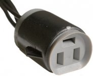
I just bought this item, Item number: 400036578358, off Ebay. It will make for a more secure and elegant connection from the GM HEI to the Duraspark dizzy.
 

Attachments

  • A20841-2T.jpg
    A20841-2T.jpg
    13.4 KB · Views: 6
Ok. so if I asked for a wiring digram of the duraspark with the hei (gm).How many would I get ?I have a 200 6 cyl with the comnplete duraspark.And this heatsink has really got me confused .What is this?( a picture of just this) Where do you get it? Thanks Ken N.
 
The DS II has 3 male connectors, and the item I ordered has the corresponding 3 females. That heatsink in my photos is actually a 2 piece unit out of an old computer power supply. You may not need it, if you use dielectric grease and attach the ECM fimly to a fender apron, or any part that doesn't get a lot of heat transferred to it. You should be able to purchase a proper heat sink at Radio Shack or any other electronics store.
 
Back
Top