Finally making some progress

cr_bobcat

Famous Member
Supporter 2018
Supporter 2021
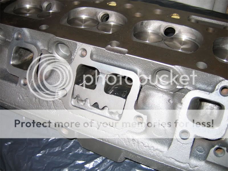
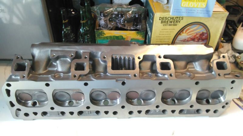
So I finally finished the rough grinding on the combustion chambers on my C9 head. I didn't measure them before starting to grind but what I ended up with in the end was:
1) 61.5 cc <- has casting flaw that is a pit. Nothin I can really do about this.
2) 61 cc
3) 61 cc
4) 61 cc
5) 61 cc
6) 62 cc <- I got a little over ambitious and accidentally ground away some of the lip opposite of the spark plug

All-in-all, I'm pretty pleased. I'm not worried about the difference on #6. I plan on pushing my CR north of 9.5 which means the head milling will make this mistake disappear. Would mean I'm just left with the 0.5 cc difference on #1. I don't think I'm going to try to do anything to balance that out at all. Think it just is what it is.

I've done some math, using data from the handbook and elsewhere, and I plan on shaving 0.070". This should put me in the 45-46 cc range. I'm not doing any block work, so with the stock pistons and a 0.050" gasket, I should be somewhere around 9.7:1. If/when I ever do any block work, I'd bore it 0.020" over and couple that with the corteco gasket I'd be sitting right around 10:1 or so. I'm completely fine with running the high-test stuff at the pump since I don't really put that many miles on the ole girl. The only real snafu I could be looking at here is valve shrouding. I've read and re-read a number of the David Vizard books/articles and am fairly confident I know what to do in order to unshroud the new valves. I'll take a hit in CR but I think any loss there will be made up with increased breathing.

So what's next? I'm going to start working the pockets and the exhaust ports. I'm also talking to Does10s and getting the 110* split profile cam (264/274), STY springs, and oversized valves. I also plan on milling off the 1 bbl boss and migrating to a 2150 2 bbl. I intend to go with the 1.21 venturi, 350 cfm version. If it all goes as planned, I should have something fairly stout.

Other than the obvious need for a complete re-curve of the distributor, does anyone see any real glaring mistakes?
 
Unshrouding the valves is a very subtle thing.
Perhaps best done by machine:

portdivider.jpg
 
I reckon that is something I can ask about when I get quotes for the machine work. If it's already in there then it might be worth the price
 
Well, parts should be on their way this week! Feel like a kid in a candy store. On the way are: 264/174 110 cam, lifters, 1.75/1.50 valves, springs, 2bbl conversion plate (2100/2150 yet to be purchased), and viton seals.

This week going to try to get the port work finished so that I can drop it off at the machine shop late in the week. I'm still trying to get the siamese port divider shaped to get it fit in. Once that is done I think I'm just about good to go.

I went to an online calculator to see where my DCR would end up. I initially used the 62* value from the cam card listed on CI's website since I don't have it yet and it hasn't been measured.

http://www.wallaceracing.com/dynamic-cr.php

The report said:
Static compression ratio of 9.5:1.
Effective stroke is 2.50 inches.
Your dynamic compression ratio is 7.62:1 .
Your dynamic cranking pressure is 149.22 PSI.

However, if I advance the cam 4* as recommended, I get:
Static compression ratio of 9.5:1.
Effective stroke is 2.58 inches.
Your dynamic compression ratio is 7.84:1 .
Your dynamic cranking pressure is 154.86 PSI.

According to the tech articles on CI, I should still be good to go with the 91 octane, which is what I can get at the pump here.

I think this also falls in with my future plans to overbore 0.020" and zero deck. This would keep me just below the 8.5 DCR threshold and yield:
Static compression ratio of 10.1:1.
Effective stroke is 2.58 inches.
Your dynamic compression ratio is 8.33:1 .
Your dynamic cranking pressure is 167.51 PSI.

Do my maths look ok? I need to make sure I'm on the right path with my machine work before I tell them to get started. I'm still planning on 0.070" off the head, which should ballpark me at 46 cc assuming the examples I've found for the approximate volume reduction for milling.
 
guh...getting frustrated. I've had the head sitting at the machinists for a couple months now. Nothing's been done because he hasn't been able to find someone willing to braise up material around the log in order to install the 2 bbl adapter. Apparently the 2 guys he has didn't want to do it. He was of the opinion that doing anything besides braising won't stand up to the heat nor will it work to hold one of the mounting screws. So...

Any recommendations on what to do from the standpoint of an epoxy/metal putty that others have used successfully for this type of thing?

He's going to go ahead and get the other work started now I asked him to mill the 1bbl boss down anyway and I'm to try to figure something out in the mean time
 
The adapter is bolted to the log head. You just need to make the connection is airtight/vacuum leak free.
I don't see why 2 part epoxy would not work ?
DannyG
 
I'm contemplating using Thermosteel to build up those areas. It's definitely rated at high enough of a a temp and indicates that it can be drilled and machined after it cures. Seems like if a slap on a coat every day for a week, I can build up the low spots enough to finish the milling/install process. Then I can use my dremel or whatever to hog out the holes.

Would this work?
1) Mill the surface flat for the adapter.
2) Drill/tap holes for screws that I can.
3) Follow what mike1157 did by coating the screws in locktite before globbing on the putty.
4) Mount the adapter.
5) Glob on dat putty including around any exposed screws. Make sure it's where I want it!
6) Sit and wait. :beer:
7) Hog out the hole

Doesn't seem like it should be "that" difficult. Am I over simplifying something?
 
No,, get busy .I had no problem sealing an adapter with only .090 of surface with a 1/6'' gasket and permatex no 2. at the narrow point.
 
"...I had no problem…"
and U saw the result MPG got?

U got a C9xxx which is real flat & should wrk great.
The one in the above pic is as good as I've ever seen
(wondered which yr when 1st displayed 4 us elsewhere).
Follow THAT regime (build up 1st B4 milling - wasn't it?) for good, solid results (in more ways than one).
:eek:
 
Make a new adapter or position the adapter so that you don't have to use the epoxy for structure - only for sealing the curvature. Make the hole in the manifold smaller or odd shaped if you have to. The material cut out of the upper left corner of the picture makes for too large of a hole for the epoxy to work. Do not use if for structural holes. There's no reason to have the opening perfect. Again, just use the epoxy to seal outside curved areas to help the gasket seal when filed flat so the epoxy piece will be in compression and be captured , like on the bottom left,and not fall inwards, in other words don't put in on the inside angles where it can be pushed into the manifold.
 
Went and talked to him yesterday. We're back on track and he's going to start cutting. Hopefully I'm just afew short weeks out from a new head!
 
On the JackFish pic -
I was about to ask what was used to smooth the divider to the "gasket surface" but it looks a lill backed up from that plane.
What's the word on that?
I was thinkin to tack it a lill proud (3 places of the 'T' shape) and use a wheel/disk to hog out a bit, then a hand file to finish up bringing it exactly level w/the 'gasket surface'.
Can anyone guide me on this as an end result/method?
 
I would try and get it close but err on the side of proud and then have the machinist surface the entire exhaust flange of the head.
 
Thanks for bringing that up. I forgot I had a divider set up to be welded in. I'll need to run that down to the shop next week.
 
Econoline":3vtaokwe said:
I would try and get it close but err on the side of proud and then have the machinist surface the entire exhaust flange of the head.
WoW, outta shop time & he trued it already I can just C goin back (not!).
I'll give it a try, as detailed, 'less some think I'll kill it.
 
chad":3ixghwrj said:
Econoline":3ixghwrj said:
I would try and get it close but err on the side of proud and then have the machinist surface the entire exhaust flange of the head.
WoW, outta shop time & he trued it already I can just C goin back (not!).
I'll give it a try, as detailed, 'less some think I'll kill it.

you can use emery paper and a heavy sheet of glass as a "sanding block" if you want to keep it flat...
 
yes sir,
some options after judicious use of power -
1st file, then emery, may B last - this glass idea & some 2-300 grit.
thank you!
 
chad":jga7gcme said:
yes sir,
some options after judicious use of power -
1st file, then emery, may B last - this glass idea & some 2-300 grit.
thank you!

If you use the glass make sure it is thick (those heavy 3/4" glass tabletops are perfect) , tape, or lightly spray adhesive the emery paper down to the glass, and sand the flange in one direction, then 90 degrees, etc... If you get nice even crosshatching over the entire surface, it is likely flat.
 
chad":n8ze6dvn said:
Econoline":n8ze6dvn said:
I would try and get it close but err on the side of proud and then have the machinist surface the entire exhaust flange of the head.
WoW, outta shop time & he trued it already I can just C goin back (not!).
I'll give it a try, as detailed, 'less some think I'll kill it.

Get a different guy

7tlmsQ.jpg
 
Back
Top