Wanted Ford 300 straight cut timing gears

Parker

Well-known member
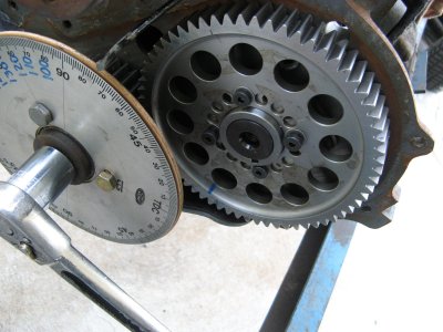
These gears were custom made many years ago by a member who is no longer active on the forum. They are simply timing gears, with straight teeth. I am in search of a set, and will continue to be until I either find some or design a new set and hire a machine shop to make them myself.

If you have a set lying around, please let me know, and if you are interested in selling them.
 
I’ve never seen a set but can help you get a set made if you run out of options.
Any idea in what neighborhood the cost would sit? I'd assume that the gears would have to be made with CAD. Let's be honest, who goes off of graphing paper anymore? I'm no good with computers, so I couldn't do any real in house development. I might hire one of those fiverr geeks to design something.
 
Any idea in what neighborhood the cost would sit? I'd assume that the gears would have to be made with CAD. Let's be honest, who goes off of graphing paper anymore? I'm no good with computers, so I couldn't do any real in house development. I might hire one of those fiverr geeks to design something.
I don’t. I would have to model it and get a quote. Cost would be dependent on design and manufacturing techniques.

I have a CAD program and a gear set I can use for measurements.
 
I don’t. I would have to model it and get a quote. Cost would be dependent on design and manufacturing techniques.

I have a CAD program and a gear set I can use for measurements.
I am intrigued. If you are able to come up with any ballpark quotes, please let me know.
 
There are pics of them in a thread or two still on here. Mikenson was the one who had them made. They were made with the cam gear being made to be adjustable.
 
Does anybody have the contact info for Mikenson? I would like to contact him regarding the set he made me.
 

Attachments

  • XFLO CAM 01.jpg
    XFLO CAM 01.jpg
    516.9 KB · Views: 17
I am intrigued. If you are able to come up with any ballpark quotes, please let me know.
Most all machined gears are done by gear hobbing or gear shaping (2 similar but different methods). If you have internal teeth, (edit) the shaping method can be used but if your internal teeth are limited to a few sizes then a broach can be used. At Jerico they used a pull broach, machine was maybe 10' long, broach 4' with the cutting teeth about 3' of that 4'. For the external teeth they used both the gear hobbing method and gear shaping. Guessing over the life of Jerico they cut maybe 20-25K gears. All were involute spline. If you closely at the tooth form on the cam timing gears on the 240/300 you will see this shape (use an eye loupe). This allows the teeth 'to roll' when gears are rotating/meshing. Drawings were kept but had minimal information. The drawing sheet had: a section drawing to show the shape and dims (of the blanks) for the removed material: OD, OAW (depth), bore (determined by the ID of the mating spline). Data printed on the drawing included: how many teeth and pressure angle (we used two PAs as I recall). The cutters needed were actually few in relation to the number of gears cut because pitch and pressure angles used were few). When changing the diameters you merely moved the cutter in relation to the CL/OD. Although we used CAD it's not necessary when cutting gears using the predominate methods. NOW, a lot of preliminary work was done before the first gear was ever cut. Since the trans was using Ford toploader dims shaft locations were known. Data the machine operator would need was printed on a spreadsheet, find the gear you were cutting and then see what change gears for the machine (ratio to get the correct number of teeth cut in one revolution of the gear blank), distance from CL of gear blank to CL of cutter, and which cutter to use. Warning, I might be omiting something here. For just a few gears you can wire EDM (about 45 cutting inches on a little over .875 wide 58T gear plus however you do the bore and keyway) but to do so you need to find out a LOT on dims that will already be taken care of you spring for a disc type cutter and it adapter for use on a Bridgeport. But along with this you would need a dividing head or precise rotary table. If you use the rotary table you will have to use a 3 digit (not the rounded off 2 digit) angle between teeth. Use the 2 digit and your last tooth will probably be off by enough to make you drop your piece in the waste can. Or a CNC 4th axis (rotary). Link for a cutter. https://www.amazon.com/HHIP-2041-1038-14-5-Degree-Cutter/dp/B0BRMLCRGK And design data for the DIY:https://www.engineersedge.com/gears/involute_spline_13649.htm IF IT WERE ME, I'd talk to a cutter manufacturer, explain what you want/need, and see if you send him a gear (new) if he will take the time to determine what cutter you need. These are actually usually on the shelf. Add the last pic. This closely resembles the shaper used at Jerico. The shaper had quick vertical strokes and removed minimal material. With each complete rotation of the blank the blank would move a little closer to the cutter. Process continued until the gear was completed. For Jerico each gear might take 10 minutes (SWAG). The center gear cutter shown is not real common but effective. Uses an adapter (R8 is one) and it is slowly plunged into the blank. Cut one complete tooth, rotate blank and cut another tooth. This method is similar to the last pic in that you cannot cut a complete tooth with one pass. However you can take big nibbles.
 

Attachments

  • involute spline.jpg
    involute spline.jpg
    25.4 KB · Views: 8
  • gear shaping cutter.jpg
    gear shaping cutter.jpg
    17.8 KB · Views: 6
  • gear-cutting-by-shaper.png
    gear-cutting-by-shaper.png
    14.7 KB · Views: 1
Last edited:
Back
Top