Turbo EFI F100 Progress

Petrol360

New member
Hello all,

Iv been enjoying this site along with the turbo sixes facebook group for a while now. I finally have made some progress on my build so I wanted to share so others can see and pass along advice where my knowledge is lacking.

I have a 1966 F100 short bed (yes the front end is from a ‘64 I know) that I picked up a few years ago. Got the truck back on the road and I have been modifying and fixing as I go. Iv put around 5k on the truck and its been great so its time to mess that up by going with a turbo on the truck! As of now the truck has a crown vic front suspension and a crown vic rear axle. The rear end has been C notched, running leaf springs with a watts link. What I believe to be the original 300ci is under the hood because the vin shows it was a factory straight six truck and the casting date on the block matches up. Behind the 300 I put a T5 5 speed and it has made the truck a dream to drive. The truck will cruse at 75mph and on the 5 hour drive to the the F100 show a month back it was getting 18mpg.

Here is how the truck started out vs. how it looks today
6E04AB22-C0ED-4C6B-AD3A-EF356CB31206.jpeg
174B065A-B16C-439D-B722-46BCB95B7B11.jpeg

The plan has always been to turbo the 300 in the truck but I wanted a solid starting point. So the last 3 years has been getting it back on the road and modified to make it a fun driver with modern day traffic.

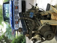
The first step to turbocharging the truck was to get a mock up motor. Something I could build the turbo kit with, without taking the truck off the road. So I sourced a rebuilt 70’s motor with 30 over pistons and brought it home. The other plan for this motor is to have a spare incase the motor in the truck looses oil pressure or something like that. I don’t want to take it of the road any longer then I have to!
Once I finish the turbo kit I plan to build the mock up motor for boost with some added ring gap, ARP hardware, and forged pistons if I can find a good set to fit it.
Im not going over the top with this turbo build the plan is not for max power but really the sound and cool factor. Plan is to run 6-8psi and turn it up to 12psi to play from time to time. My T5 won’t handle much so I will keep skinny tires as a way to save some stress on the trans.
2BD1BDAE-B795-48C9-979F-92F4953518F4.jpeg
5A03665B-B122-48BB-90EB-9571C4C357DF.jpeg
 

Attachments

  • F5EA4702-5C2E-4CE9-BFB5-5F7543E6E047.jpeg
    F5EA4702-5C2E-4CE9-BFB5-5F7543E6E047.jpeg
    141.2 KB · Views: 6
There are so many options for turbos now but I ended up going with a VS Racing 67/62 gen2 journal bearing turbo. Its definitely big for my goals but again im not looking for max power or response. So some boost lag is fine by me. I wanted a large frame turbo without a built in waste gate just for looks if I'm being honest.
A24D614F-4658-4859-8A5C-9FC097D37FCF.jpeg

This turbo has a .82 exhaust housing with a 3” vband outlet and a T4 inlet. I figured the smaller exhaust side should help keep the spool time reasonable. But we will all have to wait and see!

After lots of planning and scheming I came across the exhaust flanges from Stainless Headers made for the 300 and impulse bought them. After looking at the options on manifolds I figured why not go off the deep end and build my own. So after a month it showed up in the mail.
2322A40A-7FE2-4829-8FCD-84F4D01C3DE5.jpeg

The next step was planning out how to actually build the manifold. So I did some digging and ended up with some sch10 stainless pipe and a general idea of what I was looking to build so I placed my order and patiently waited for parts to come in.
9C5D0049-1900-4F56-A97C-A48679F73B74.jpeg
BD8F3D97-6112-4328-AACB-84954D3CA1DB.jpeg
FF0E8E32-A608-4EE1-8989-AB7AA064A0AC.jpeg
 
So I started to mock up the manifold but then realized I also needed to look at the intake so both would work together. The intake manifold will determine the turbo placement in the truck. The turbo placement will determine the manifold design, so working a bit backwards to start. My original plan (and still my back up plan) was to run a Holley sniper efi on the offenhauser intake that I have in the truck. I could control timing with the sniper and add a boost reference fuel regulator and go from there.

5C1BF7EA-6613-411F-9CB6-30865962D278.jpeg

While mocking up the manifold and using the factory cast manifold that the mock up motor came with I somehow went down the rabbit hole of going all in with the EFI system. Running sequential injection and coil near plug spark. Give the motor more tech then a 300 ever got from the factory. So I decided to give it a shot and see where it goes.

After looking at intake options I decided to borrow a design I saw on the Facebook group and use the factory lower efi intake and build a custom plenum to go on top. This will make my life easy so I can use the factory fuel rail and injectors ports but still have a custom look like I want.

92B386BD-31E5-408E-AB99-569149926E52.jpeg

So after spending way to much time and money at a junkyard I brought home a lower intake and fuel rail. The factory design made my life easy, or at least my idea. I know the factory upper manifold is a good design but I want this motor to looks custom and the factory upper is just ugly…

So this is where I am going with it!
F0DAD704-F4D9-4155-A969-6D73476F380D.jpeg
FCFB90C9-E05B-4F6F-A910-D4D9DED9F46C.jpeg
1EE48D9D-ADAE-4FD6-8103-059C85252BD5.jpeg

You can find extruded aluminum in different shapes on ebay that is made for building intakes. I chose the 5” “D” shaped design and ordered up the length I needed. I put a 45° notch on the back to give it some shape, again going to as custom of a look as I can.
I also decided to run a throttle body from a LSX motor. It seemed like the easy button, lots of options in the aftermarket and lots of support on the tuning side.
Photos are just of the mock up, I am still currently waiting on a few more parts before doing any welding on it.

A7349F3E-D3A8-4466-8960-3C03E2A47462.jpeg
8F2EF239-462A-430E-9F2D-6DE9B39B3386.jpeg

Last night I punched some holes for the bolts and runners. Thankfully I was able to do a decent job matching the ports. All this was done by hand so lots of room for errors. Next i plan to shape the inside of the ports for better flow, or find some cheap velocity stacks to add inside the plenum to help with flow into the runners. Either way I am happy so far with the progress.
 
Looks really good! That upper intake is basically what I am planning to do on mine too, you just beat me to the punch!

That truck also has a killer stance - I love it
 
Thanks! @jgavac I'm excited to see how it will look when its all wrapped up!

Now im starting to dive into the signal side for the ignition system. I know I will need a crank trigger wheel, but I haven't found many photos of others setups for our motors. I know it will need to be custom but I would love to see how other have made them work. The other peice is the cam signal. I was going to modify a stock distributor and add a 1 tooth signal wheel and a Holley sensor. But after looking into the Holley software I can set up the EFI system to only look at the cam signal during cranking. So once its synced it ignores the cam signal.

Knowing this I thought about using the fuel pump lobe on the camshaft for the cam trigger. With it being an egg shaped lobe I know some people worried about the accuracy of the signal it would provide at RPM. But if I only need a signal during cranking to let the ECU know what cycle the crank is in then I think that may work. Food for thought at least!
 
If you are going to use a serpentine belt, the 1996 harmonic balancer has a 3 tooth wheel on the back that can be replaced with a 60-2 wheel.
The EFI engine TFI distributor has a 6 vane Hall Effect signal that will work very well for a cam sync signal if 5 of the vanes are removed.
Clintonvillian made an aluminum cover to replace the distributor cap on his.
It looks good and will allow you to time the pulse wherever it needs to be.
 
You can definitely use the pump lobe as the cam sync, you'd just need a way to drive the oil pump. The other option is sourcing a stock TFI distributor and using the sensor in that with a block off plate. A few of us have looked at other options, such as using a later model V6 cam sync sensor (me), or modifying a holley V8 sensor (others), or a custom made cam sync sensor (me and others) - without any luck.

20230327_164108.jpg

For the crank trigger, I also haven't found a solid solution yet. I have a triple stack harmonic balancer, so I'm going to see about having the trigger pattern milled into the very front. I've seen another build where the crank trigger was milled into the flywheel, which is another option I considered.
 
94C44BE5-4A5B-43F1-B4BF-010EFE4F1CD6.jpeg

I have been making progress on the timing portion of the build. Iv made progress on the cam sensor but nothing to post on yet. I do have parts in hand for the crank sensor. As other have said a harmonic balancer from a ‘96 has the ability to mount a trigger wheel to it. Photo above is a balancer from a ‘90’s truck I picked up from the junk yard but obviously it would be difficult to mount a trigger wheel to it.
02B71128-3C4D-4DD9-8EA1-C4A3ADF204D2.jpeg

Thankfully RockAuto sells the balancer I need, much easier then trying to track down a used one!

So this balancer has space to mount the trigger wheel as well as a second set of mounting holes for it. Next will be having the trigger wheel sized and cut to fit. Thankfully the internet makes it very easy to do that now. There is an online site that I can plug the specs into and they will cut a custom wheel to fit.

FF248F2A-A6E3-421E-9977-D8812F880CD7.jpeg
55231E25-0AEF-4438-AAA0-E7B369FCB9F6.jpeg
3C6FB899-761B-4106-8ED4-E58CBE2426F5.jpeg
1735C0B7-74FB-4737-92B5-F1CDA3F5C53E.jpeg

More progress on the turbo system itself. The intake is almost finished up, just needs a throttle bracket. I also added a GM style map sensor so I can add a 2.5bar sensor for boost. The intake is made of some thick aluminum so I was almost maxing out my welder to get everything assembled. I started back on the exhaust manifold as well. I got the #1 runner mounted and routed past the intake as well as the alternator bracket. The next steps for the exhaust should be much quicker. Coping the other runners to the main log will be a pit of a challenge though.
 
It looks like you are through bolting the plenum to the runners. Is that correct? If so, how do you plan on sealing it from leaks?
 
It looks like you are through bolting the plenum to the runners. Is that correct? If so, how do you plan on sealing it from leaks?
Just using the standard gasket like the factory uses between the upper and lower intakes. Part of the reason I used the factory lower is to keep things as simple as I could.
 
There is a difference in your design and the original. The bolts are completely external on the ford design, so they don’t need to be air tight. Are you following?
 
There is a difference in your design and the original. The bolts are completely external on the ford design, so they don’t need to be air tight. Are you following?
Yep I know what you mean, i am going to use a thread sealer on the bolts. That should be enough. If I am fighting leaks I will weld in threaded inserts into the intake. A bit more work but I believe the thread will be fine.
 
Time for an update on the slow progress!

Been slowly working on the manifold. This really pushed my tig welding skills! Running in all kids of crazy positions with lots of tungsten hanging out of the touch just to get in tight places. This was my first stainless project and im happy to say my back purging was successful! No sugar on the inside although I could of had more penetration.

IMG_8881.jpeg

IMG_8967.jpeg

IMG_8968.jpeg

0O6A8355.jpeg

0O6A8361.jpeg
 
My welds aren’t bright and shiny but they improved as I went. Im definitely glad I went with schedule 10 pipe there is no way I could have done this with thin wall. I also hope the thicker wall won’t be as prone to cracking.

0O6A8370.jpeg

0O6A8369.jpeg

The plan is to weld a Vband to the end of the manifold as it sits now then build a up pipe to the turbo. This may give me better options for wastegate and changing the system later down the road. Or if I don’t keep this manifold long term someone else can make this fit there application.
 
With the manifold mostly completed I got some motivation to mock the turbo in the truck. So I got creative with zip ties and scrap metal and built a mount. I am running the turbo high on the drivers side. Mostly due to packing but also because I want the turbo in your face when you pop the hood.

0O6A8385.jpeg

0O6A8386.jpeg

0O6A8391.jpeg


0O6A8393.jpeg

I am going to build the up pipe off the tuck on my mock up motor. So I made some brackets coming off the motor so I could keep track of the position in reference to the block. I used a mild steel T4 flange and welded some mounts from scrap metal so I have a target to shoot for.

0O6A8398.jpeg

0O6A8400.jpeg

0O6A8395.jpeg

So this gives me a great visual for the up pipe. Now I can plan of the pipe and get some more sizes ordered.

I have the EFI manifold back on for mock up but I believe I am going to run a sniper EFI first. Just to keep things simple. I am also planning on having the turbo in the truck for F100 nationals in a few months.

Thankfully this progress has gotten me excited again on this project!
 
Nice build! Very cool and very familiar. Just catching-up, so...
My plan is to hack a stock distributor down to just the shaft then place a cap on it to make it look clean. You still need something to run the oil pump.
These are some distributors I cut, and they get a tiny Hall sensor into the side to read a notch on the shaft for a single pulse per-cycle. The middle one got a cylinder position indicator to the shaft on top, engraved at the trophy shop, making stuff like TDC compression stroke or lashing valves easy. The shorty needed a little sealed top bearing as the shaft was too short for the bushings.

Stub cut distributors.jpg

All that, and then I did a full distributor body with a 75mm 36-1 wheel, as some systems can trigger full-sequential if the wheel is in the distributor at half-speed, making the missing tooth the cycle signal for cylinder identification:

Gpineau_36-1_DIST_wheel.jpg

But I'm thinking the easiest would be to mill slots in the balancer ring if it is not rubber damped to that ring. Probably well under $50 at a machine shop using a divider head for accuracy. If it is rubber damped on that ring, then machining a rabbet on the back of the solid damper center for a toothed wheel. The goal IMO is to keep the sensor back where a thrown belt won't destroy it. Lots of options to chew on!

300_damper.jpeg
 
Thanks! Yep my idea is to weld an aluminum holder for a LS based cam sensor to the factory distributor housing. Iv already got the aluminum machined so I will just need to modify the distributor to hold the sensor and a single tooth wheel.

Rockauto still sells the later model 300 balancer that is shorter and will hold a tooth ring for crank signal.

There is a website that you can give the trigger wheel specs and the will lazer cut one for you. Any diameter, any tooth count, any center bore, any mounting bolt pattern. I haven’t ordered one yet but it was super easy to spec one out and very well priced.
 
Back
Top