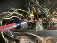
Engine running much smoother, carb set well and drove around the block. Think it just needed to wake up! Running on load a matic and Autolite 1101 Thinking my remanufactured advanced distributer should be here any day. I am close to putting the gauge panel back in place but thinking I should get the wiring right on my electronic ignition harness. My ignition switch seems to have five wires coming out. Yellow, pink (or red), another pink (or red), black w/ green stripe and black. Attached is a couple pics. From what I can tell with the mustang Steve printout I have four wires (after plug connection fitted). The yellow would go to a tachometer. The red goes to + on coil, or can connect on engine side of firewall, maybe splice near firewall plug.? white goes to “S” terminal of starter relay. Brown I am at a loss as to where it goes.
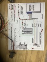
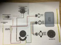
I have two diagrams. The mustang Steve diagram and this that came with harness
I have two diagrams. The mustang Steve diagram and this that came with harness
") ; with some effort you can do it on your engine with timing tape (degree markings), a timing light and a hand vacuum pump, if you're strapped or time-limited. Yeah, the way hot rodders used to do it for best results with your engine and your fuel in your conditions.
; with some effort you can do it on your engine with timing tape (degree markings), a timing light and a hand vacuum pump, if you're strapped or time-limited. Yeah, the way hot rodders used to do it for best results with your engine and your fuel in your conditions. ")


