chessterd5":3s6wbsql said:
Hello xctasy, I think I'm getting it. The closer you get each individual cylinder to running like it's its own engine, in harmony with each other sharing a common crank, the better the overall performance will be?
Is there a formula for determining proper intake runner length?
If I understood all this right, using a 300 I6 as example:
1) you need the size of the cylinder which is 50cid or 820 cc.
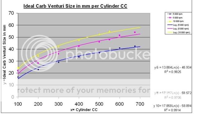
2) you need the size of the venturi to match cylinder capacity. By your chart above, I'm guessing that to be either 48 or 49 mm which is 1.89" & 1.92" ( which is also the suggested size for intake valves on a 300. Chevy 1.96 cut down to 1.90.)
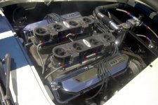
3) You need the length & diameter of the intake runner from the carburation to the valve cause technically the intake port in the head IS part of the intake runner. The Preperation H car used 1.75" tubing & the carb horn was 18" away from the valve seat by the article. Does this still hold true now? Or should the diameter of the intake tubing match the size of the venturi as well as the size of the intake valve (about 1.90")?
4) Cam size: cause this affects cylinder capacity, right? & the vacuum signal to the carb telling it to "refill" the cylinder, right? & when the intake valve opens & closes?
So, what size cam matches (as a baseline) a basically stock 300, ported to flow lets say 210 cfm & a 6000 rpm limit using the port on port I/R carburation we're discussing.
I couldn't find lift & hp #'s on the Stan Weiss site so I can't calculate what 100% of peak flow for cam & heads means. I'm sorry I'm dumb but I'm trying.
Item 1 and 2 are bang on...that is it totally, nothing else. The line for 6000, 7000 and 8000 rpm is a function of the volumetric efficiency line from Stan Weiss site
Last notes on cam, Item 4, is partly the cfm at max lift, but isn't needed, as item 3 4, and the last concern over cam governs that peak power rpm anyway.
See
http://users.erols.com/srweiss/tablehdp.htm for
Cylinder Head Flow Data at 28 Inches of Water
How to use the RPM of Peak Horse power Table.
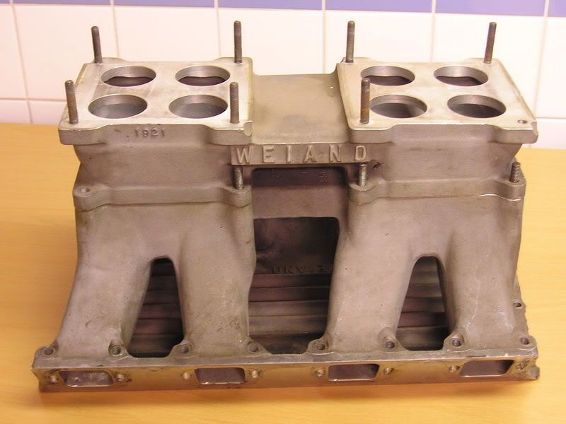
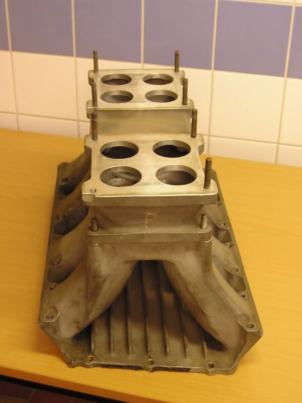
All those important questions you raised are non matters for the graph, only item 1 and 2 are. The curves won't be made if the cam and carb aren't right for that selected venturi and cylinder capacity. It then tells you the rpm range at maximum power, and what reults will work, even if you had the wrong sized intake runner volumes, cross sectional area and carb entry distance. They are minor matters. As I state later, our Falcon 250's from 1971 log, to 1971 2v non cross flow, to 1976-1980 iron cross flow to 1981-1992 cross flow varied 25% in size and 50% in runner length, with the last heads being smaller in runner than the 2V 250 head, yet yielding better flow. So a 2-bbl direct log, 2v 250, iron x flow and alloy x-flow with the same 2-bbl carb all yield the same 149 flywheel hp at 3800 rpm with the same cam and single tube header exhast. In a 3000 pound car with a four speed and 2.92 diff, 16.9 seconds for a quarter mile comes up irrespective of the intake manifolding, weather an 1972 XY Falcon GS or a 1982 XE Falcon GL...the intake geometrics are not a major factor.
This is why I don't ever get into carb entry distance (Ced),volume of intake (Vi, cross section and length based) and Cross sectional area (Xa, cross section and length based) because you first have to build an independent runner system to fit the engine and engine bay, and hood limitations means you can't run the optimum lengths in any direction. Just like tube headers, its what fits, not what the formula recommends, a very important engineering principal. The Pipe Max program gives you 1st to 8th harmonic optimizations, with the 3rd order ones often the best. Pipe Max covers off a little of what the RamChargers found, but Amal carbs found it out years before those Mopar engineers. Tunnel ramming and POPIR (port on port, independent runner) systems are subsets when they are down drafted, but the Mopar system is varies due to the internal passages direction. Ram Charger Firepowers were down drafted, whereas early 413/426 Max Wedge cross rams were side draft AFB's, while the later ProStockers were down draft Dominators, so the degree of supercharge due to gravity was heaps higher in the early De Soto and later Hemi 426 intakes.
From
https://fordsix.com/forum/viewtopic.php?f=5&t=31668 on » Mon Jun 27, 2011
For me, the variables Vi and Ced and Xa define the nature of the intakes ability to optimize or limit fuel standoff after a basic combination has been ratifed. See below.
Primarily, before discussing those three basic geometric design parameters above, your always stuck with a basic form to test, and then optimize, for in engine development, you always use horse trade from the existing base to the evolutionary optimum. In terms of blue printing options which help, then port miss-matching makes the best fuel standoff preventer you can get. Take for example the antipodean Alloy Head cross flow 4.1 with its 1.3" port, or the iron 250 2V with its 1.65" diameter intake port, or the iron cross flow 4.1 with its 1.38" port. Each is circular, but has a manifold which is often sharply formed and of a lessor diameter than the intake port. Result is no loss of air flow compared to a perfectly port matched intake, but better fuel atomization, and, if one of the common Aussie sedan racer or speedway triple Weber installations is used, you can gain significant mid range torque with no loss of high end power. If the manifold has a 60 thou annular size reduction on intake port, and even better, a 30 degree chamfer, reversion is reduced significantly.
Secondly, you then go to what I think is the Amal information used in port volume and distance to intake. Vincent motor cycles engineering technician Phil Irving had that stuff worked out brilliantly. Repco 2.5 Formal 1 engine optimized those settings. Apparently, according to the Chamerlain brothers account back in 1979, engines suddenly come alive when the reflecting waves are controlled by maintaining intake volumes (Vi) and intake to carb entry distance (Ced) to certain limits. A lot like the famed paint the pipe with acrylic, and saw the exhaust off where the paint stops burning maxims from motorbike tuners. I assume fuel standoff is a definable quotient when the 1st, 2nd,3rd and nth degree order resonances are worked out, and that fuel standoff is actually just a function of air pressure bank-up. So Vi and Ced create an ideal tune.
Phil Irving and others define a flow net geometry cross section, where the number of flow drops to flow paths should form a lattice of squares with orthogonal (90 degree) lines, and from that, pressure gradient is made more even. Basically, the cross sectional area (Xa) can only vary a certain amount from venturi to the intake valve to educe standing wave propitiations.
One other thing. Seams like downdraft installations make a better power curve if they a packaged within the confines of variables Vi and Ced and Xa and IR peak power rpm
For Pipe Max, and how accurate it is, see this BMW M20 engine post...
http://speedtalk.com/forum/viewtopic.ph ... 2&start=15
Its have six pages, the link starts on page 2 and is a big read, but spend some time and have some fun...its the small Bimmer six made from 1977 to 1993 or so which the 1986 on wards 325e and 325Is were based. The little six intake in EFi or multiple carb is is crested out by shock towers hood and brake booster, but there is all manner of simulation programs to assess the right Va, Vi, Ced and any anything else. Despite the size, a well worked little Bimmer I6 head is similar to our Falcon six head engines. The guys have attempted to reconcile hp readings way better than expected, and the Pipe Max doesn't even show what is possible with a really well sorted intake.