You are using an out of date browser. It may not display this or other websites correctly.
You should upgrade or use an alternative browser.
You should upgrade or use an alternative browser.
Bosch Distributor
- Thread starter addo
- Start date

A
Anonymous
Guest
Adam in looking at this pic it doesn't look like the same one thats on my engine
Theres about 10-15 bosch part numbers for this type of dizzy as the differ from each other slightly.They differ from 3.3 manual to auto and 4.1 manual to auto .This is probably a difference in advance weights and springs .Most parts are the same but the main shaft seems to be the main difference.They used to have them as an complete off the shelf replacement back in the good old days when i was a young fella doin parts,but there now no longer in production.
Dave
Dave
ZC-Cruiser
Well-known member
I saw an Alfa the other day that used the same module except that it was mounted to the side of the engine bay with a cable to the dizzy.
Has anyone tried making a cable and mounting the module remotely to get it away from the heat and vibration??
Has anyone tried making a cable and mounting the module remotely to get it away from the heat and vibration??
ZC-Cruiser
Well-known member
hmmm - maybe some nice coax for that...
I'm going to have a lot closer look at that Alfa - check inside the dizzy and what sort of cable it is.
It looks like a factory job - no place for the module to mount on the dizzy.
I'm going to have a lot closer look at that Alfa - check inside the dizzy and what sort of cable it is.
It looks like a factory job - no place for the module to mount on the dizzy.
Not coax! It's a sinusoidal wave AC output and coax will screw it up. It modulates the module (I know that sounds funny ") ) and this would be massively compromised. You need good shielding as well, for accuracy. You can get mini twin core with braid for inside hi-fi amps, usually the wire is silver alloy. Mike lead is just pretty rugged by comparison.
) and this would be massively compromised. You need good shielding as well, for accuracy. You can get mini twin core with braid for inside hi-fi amps, usually the wire is silver alloy. Mike lead is just pretty rugged by comparison.
) and this would be massively compromised. You need good shielding as well, for accuracy. You can get mini twin core with braid for inside hi-fi amps, usually the wire is silver alloy. Mike lead is just pretty rugged by comparison.
A
Anonymous
Guest
JDR":3hl0vbtt said:Adam in looking at this pic it doesn't look like the same one thats on my engine
nope. :roll:


ZC-Cruiser
Well-known member
maybe something like the dizzy leads on a late model XF with the EST brain box - maybe even using one of those dizzys with the simple module instead of the EST box...addo":2zyumx0u said:Not coax! It's a sinusoidal wave AC output and coax will screw it up. It modulates the module (I know that sounds funny
73GreenMachine
Well-known member
Has anyone got any experience on getting these recurved. I'm running a 200ci pre crossflow and Toyota 4 speed manual with this distributer. The advance pattern seems wrong at the moment. I've checked out the vac advance and its alright. For some reason atm it likes to run at about 15degrees advance to run right. Any less and the rpms float all over the place and it dies when you give it throttle. Will the 3.3 manual advance pattern help solve the problem? If not, how do I go about fixing it?
73GreenMachine
Well-known member
Yeah the counter weight springs seem alright. I gave the dizzy a bit of a clean the other day and it appears the advance was sticking a bit before. I cleaned it up and tried putting my old points dizzy springs, but I don't think that worked either. The Bosch distributer was out of an XD falcon 4.1 auto.
There is a place I send them, but I don't post it here. Reason is, some "entrepreneur" will appoint themselves sole distributor to the uninformed, and whack a markup on it.
PM me if you want to mail it there and I'll give you details. Be warned they may want to rebuild it too so you could be out $275. They have done five dizzies for me and I am happy with the results.
(One is a "startup" distributor - '68 points unit, fully reco'd. It guarantees a spark for first run of a new motor. A lot of people follow the cam lube instructions etc etc and then wipe it all off cranking the motor forever because it won't fire. I expect a motor to start within 720 crank degrees.)
Cheers, Adam.
addo":353wch8y said:You'd want to use pretty snazzy wire for the pickup to module leads. The output is so small (especially at low RPMs). Twin core shielded mike lead from a proper PA or music repair shop would work.
Hi guys, I'm putting a 4.0 EL motor in my XD and am running an XE dissy with vac and mechanical advance. I have mounted the module on the inner skirt on a small finned heatsink. The main reason I moved it is that there is no room at the block for both the module and Vac pot. With the module casting cut of the dissy, I can actually advance it.
Anyway my question to you Adam, (this might sound stupid), do you mean the two small black wires? and will the shielded wires from the original EL engine loom to dissy be OK? It's only about 12 inches from the distributor to where I have the module mounted.
Cheers for Beers.
Yes. Earth the shielding to the body at one end only. Keep the cable run as short as possible without stressing it (support as required). Specially keep far from the plugs as you can.
Next time you see a dumped early Magna or Corolla, steal the module. It's identical and a spare is nice. But please make sure the car is dumped, not just parked. :roll:
Next time you see a dumped early Magna or Corolla, steal the module. It's identical and a spare is nice. But please make sure the car is dumped, not just parked. :roll:
A
Anonymous
Guest
Does anyone know exactly what needs to be modified in order to run one of these in a precrossflow 221? Can you fit an early shaft straight into the dizzy housing or can you simply press a bush onto the bottom of the shaft or do you need to turn/drill out housing to take the early shaft?
One other thing, (I just got one (XD 4.1) from the self serve wreckers today) I can't seem to find a way to remove the internal coil thing and the magnetic ring thing in order to remove the hex head bolts etc. How do you get these apart?
Any info appreciated.
Cameron.
One other thing, (I just got one (XD 4.1) from the self serve wreckers today) I can't seem to find a way to remove the internal coil thing and the magnetic ring thing in order to remove the hex head bolts etc. How do you get these apart?
Any info appreciated.
Cameron.
Mr Milne!
Where have you been?
This is from an (illustrated) guide I wrote some years ago.
This help?
Where have you been?
This is from an (illustrated) guide I wrote some years ago.
In Rough Form
This is not a guide for complete novices. It assumes
1. Commonsense
2. A fair smattering of tools available
3. Proficiency with those tools
4. Patience and observational skills
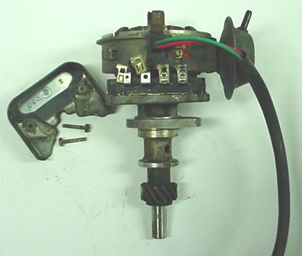
Start with the complete unit – either from a wrecker, or off the car. Remove the cap, rotor and cap spacer where fitted.
Unclip the coil from the wiring if not done already. Undo the coil bracket, and unclip the suppressor. Clean the coil, bracket and suppressor with Prepsol and paper towel.
STORE THE COIL UPRIGHT OR IT WILL LEAK
Then it may not have enough cooling oil, and burn out fast.
Now for the distributor.
Clean the exterior amply with Prepsol and paper towel. Avoid any cleaning or solvent sprays at this point. Scrape heavy grunge away with a flat bladed screwdriver. Your unit should be now 90% clean on the outside; maybe some brownish tarry stains from oil, maybe some oxidisation of the alloy.
Unscrew the cover of the module. The screws have no washers. Unplug the module. You may need to hook a small flat bladed driver or bradawl into the Utilux clips to slide them off. The module can be removed by hand now – just lift the locating pins clear of the metal it sits on. The output wire grommet (black, rectangular) can be prised or pulled up and out of its slot in the side of the distributor body; now the red and green wires are free.
Clean the module cover, mounting screws, output lead and module with the Prepsol and paper towel.
• Note that the module has silicone grease on the base for heat transfer assistance. You may wish to be careful not to contaminate other things to be painted, by scrubbing up thoroughly at the completion of cleaning the parts.
Next to go is the vacuum modulator. Remove the two screws with attached washers, and the modulator will flop around on the side of the distributor.
TAKE CARE NOT TO TWIST THE UNIT
Now, look in the side of the distributor where the output wires' grommet was removed, and you will see the end of the vacuum module control arm. A thin, small flat blade screwdriver is handy here. You need to prise the arm downwards from its inverted pin on the (breakerless) "breaker" plate. There is no circlip or split pin, it just gently is worked down and free. The vacuum modulator can then be removed and cleaned.
It's getting more fun by the minute. Now clamp the distributor shaft end in a soft-jawed vice (wood, nylon or aluminium jaws are fine), standing it upright.
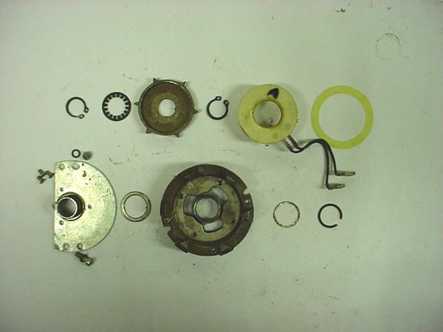
There is a circlip type clip at the centre top which has to be prised off. It will want to spin around; stop one end with a flat bladed screwdriver while you prise the other out of its groove, little by little. A smear of oil on the shaft (usually rusty) will help you slide it up and off. Remove the spring "finger" washer underneath.
Remove the distributor from the vice. Using a smaller hammer (Warrington or cross-pein is ideal) with about a 1" face, tap the upper shaft end firmly while holding the unit in your hand, at the gear end. With repeated tapping, you will see the star-shaped inductor slide up the shaft, and eventually be removable.
Below it is another circlip, same as the first. Remove in a similar manner, noting that it has to pass over the first clip's groove, so twice the fun.
AT ALL TIMES TAKE CARE NOT TO FORCE OR PRY AGAINST THE PICKUP COIL. IT IS FRAIL AND EXPENSIVE.
Place the distributor sunny side up in the vice again. By rotating the breaker plate, you will see two Allen head bolts through slots in the plate edges. Loosen and remove these with a 3mm key. The plate with attached coil can now be lifted out.
Turn this assembly over on the bench, and using a well-fitted screwdriver, remove the three brass crews securing the coil. Place the coil to one side for safekeeping. Prise the c-clip from the top centre of the breaker assembly, remove the two flat washers below it, separate the upper and lower breaker parts and remove the thin flat washer from the underside of the mutual friction surface.
Clean the washers, and both parts of the plate assembly.
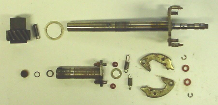
Remove the distributor from the vice again, and support the drive gear plain section on block of hardwood, while driving out the rollpin. The gear can be gently tapped off the shaft, and there may be a flat washer at the upper end, against the alloy casting. Clean the gear, shaft end and rollpin. Lift the shaft assembly free of the housing. Note there is a thin thrust washer in the upper housing, that may be either stuck to the steel bush in the casting, or clinging to the underside of the advance system.
Remove the tiny oblong cover from the side of the distributor body by prying free; it and the housing can now be fully cleaned.
You are now left with the central shaft assembly, from which the counterweight springs can be carefully prised. Next to remove are the E-clips holding the counterweights on, the counterweights themselves and nylon washers below. Clean all and set aside.
At the top of the shaft, pick out the felt disc with a sharp tool. Keep it as intact as possible. The next step is one of the hardest. Clamp the upper part (above the weights) of the shaft in the vice, so that you can aim a flooring punch down the shaft hole at the top. Centre your punch, and with several firm blows, drive the lower section of the shaft free.
Be careful to not lose the c-clip or flat washer from inside this upper shaft hole. Twist off the plastic advance limiter sleeves from the upper shaft. Clean the parts, and you are done with the dismantling.
This help?
A
Anonymous
Guest
here and there. quit uni and started a toolmaking apprenticeship, which I'm enjoying a lot more.Where have you been?
Got the XT on the road and its now my dailydriver
. still saving for a paint job though (on an apprentice wage, fuel is a killer!).Yes alot, thankyou!This help?
Would't know how to alter it though would you? I haven't checked myself but I've heard that the bottom bit of the shaft is larger on the pre X-flow and so it needs to be modified.
You need a sacrificial dizzy XY-XB. Keep the '68 unit whole as a startup/spare one. I always say to start a new motor with a points unit, as it's 100% guaranteed to fire.
The shaft from the sacrificial dizzy is TIG'ed to the advance plate of the XE unit, which is rebushed or reamed to fit the upsize. Main reason for doing this way is it's rebushing at the same time, so wear's eliminated. The hold-down collar is turned to match the '68 unit - thinner and smaller. Use an appropriate driven gear against the cam.
That and bypassing the resistive wire, are pretty much the main details to your install. It's often a mongrel to get the hold-down clamp bolt threaded in while simultaneously dropping the unit home, but once you have a feel for it - no problem. Having a helper to rock the balancer pulley slightly, can assist.
If you pull the dizzy right down, you need to make a tool for reinstalling the clip inside the rotor shaft bore. It's a hollow mandrel - nothing fancy.
If the electronic dizzy is in reasonable condition (not needing a rebush), you might be able to just make a thick sleeve for the shaft end - depends on your skill and facilities at work.
Actual recurving gets to be fun. It's beyond the scope of what I feel comfortable with. You need to run enough advance to max your possible torque peak (200 RPM below your shift point, typically) but not come in fully, too soon before. Add to that the need for negligible mech advance off-idle and you have two end-points... The bit in the middle is territory for either a dyno or skilled hand.
I'll try to get pictures of the spare 221-converted dizzy I've got here. Waiting to build an engine around it. :roll:
Catch ya later.
Similar threads
- Replies
- 3
- Views
- 3K
- Replies
- 1
- Views
- 344