I spent a little time Monday night doing some wiring on the Falcon, but not much because it was cold and dark and I remembered I had a 7:30p dinner. I was pretty hasty in my assembly but following the diagrams on Autosport Labs was not difficult. I sprayed some carb cleaner in the carb and turned it over... it stuttered, halted, and backfired. Something was wrong. I double checked my wiring and it was *exactly* as indicated, so I figured the indications were wrong.
After dinner, I spent many hours googling as many wiring diagrams for '95-'05 V6 cars and trucks as I could. I was kind of shocked in that Ranger owners by far and away had more information posted on Ford V6s than any other single model. Ranger forums across the world were very helpful!
A bunch of technical stuff that nobody probably cares about:
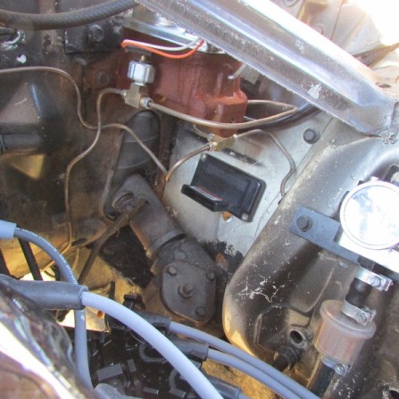
ALL the documentation for Megasquirt and Megajolt label the coil towers left to right, with the connector facing the viewer. This is not how Ford labels the towers. Additionally, the Megajolt (and I assume Megasquirt) shows the connection of EDIS to the coilpack in a different order than Ford does. In combination this double-mislabeling works, but if you're trying to compare Ford wiring diagrams and Ford-labeled parts to what you're doing, it doesn't.
Also, Ford sold two virtually identical versions of the six cylinder coil pack - one with power on the #1 pin, and one with power on #4. I can't see any outward difference between the two, and even worse they used both at the same time, just in different vehicular applications. A '96 Mustang 3.8l V6 or a '98 F-150 4.2 V6 has the power on #4 (as the Megajolt installation manual shows), a '90-'11 Ranger 4.0 V6 has power on #1. So, there doesn't appear to be any obvious year split. ALL the MJ & MS documentation assumes you've got a coil pack with power on #4. You have to know where your coil came from in order to know!
In factory manuals, Ford labels the coil IN FIRING ORDER, not simply left to right as MS and MJ do. With the coil pack connector facing the viewer, MS & MJ just label them A,B,C (left to right), and then state the coil pack is fired A,C,B. That makes ZERO sense. Ford labels the towers B,C,A or 2,3,1 from left to right, so firing order makes a far more sensical A,B,C or 1,2,3. The pins on the coil are ordered the same. Once you have located/eliminated the correct power pin, the left pin is left tower, middle pin in middle tower, right pin is right tower.
In the end, it doesn't matter which tower is which letter or number, and here's why: Each pair of towers (remember, this is wasted spark) is triggered by a specific output from the EDIS ("ignition control") module. EDIS fires Pin 10, then pin 12, then pin 11. You can connect 10,11,12 to whichever coil pack pins you want SO LONG AS YOU KNOW WHAT YOU'VE DONE and plug in your spark plug wires accordingly.
I have not found this simple fact in any documentation for either system, just a lot of "if you do it this way you'll be okay." The problem with that if you actually look at the parts and their factory labeling, it seems in opposition to what the install guides are telling you to do. If you noodle on it for a while, it'll make sense... but why not just tell technically minded people who are doing something pretty complex in the first place the truth!? This becomes double troublesome since there is no acknowledgement of the "other" ignition coil... the one with power on pin #1 instead of pin #4! If you've got one of those, everything falls apart.
Once I discovered there were two versions of the coil that look virtually identical and confirmed how EDIS interacts with the coil, everything made sense. Bottom line is that if you follow the MJ or MS installation manual AND have a coil with power on #4 AND connect EDIS to the coil pack as described everything will be fine.
HOWEVER, if you have power on Pin #1 and/or you ever want to use any Ford literature to troubleshoot following those instructions will just cause confusion and, in my case, total failure.
The PROPER way to wire these things up is:
Coil Power on Pin 4: EDIS 10,11,12 to coil pack 3,2,1 resp.
Coil Power on Pin 1: EDIS 10,11,12 to coil pack 4,3,2 resp.
That wiring mirrors the factory!
So I did that. And it started right up and set into a damn decent idle!
http://www.sacsaabs.org/sacsaabs.org/co ... art_sm.mp4
This is a cold start - the car hasn't moved since Saturday and had been idling just long enough for me to power on the camera. It's about 45 degrees outside. The car is running on EDIS6 in "limp home mode." Megajolt is not connected, so timing is a static 10 (IIRC) degrees BTDC. I wanted to be sure my VR sensor could sense the trigger wheel and my used EDIS module was working before introducing complications. Clearly, it is!
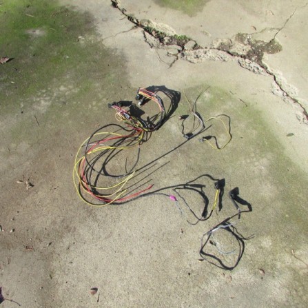
All the wiring is literally just twisted together and electrical taped right now, so tonight I am going to make those connections permanent with proper wire lengths, etc. I'll probably wait until the weekend to actually install the Megajolt controller. Aside from the timing maps, the hard part of this project is DONE.
") Hopefully the weather holds out. I'll drive the Falcon in the cold, but not in the rain.
Hopefully the weather holds out. I'll drive the Falcon in the cold, but not in the rain.
") I think it's safe to say that if the CI DUI is good for +15hp, this setup must good for at least that.
I think it's safe to say that if the CI DUI is good for +15hp, this setup must good for at least that.