XPLOED Road Roughness Project

xctasy

5K+
VIP
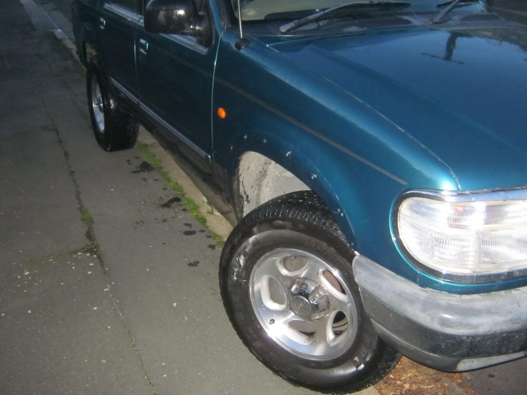
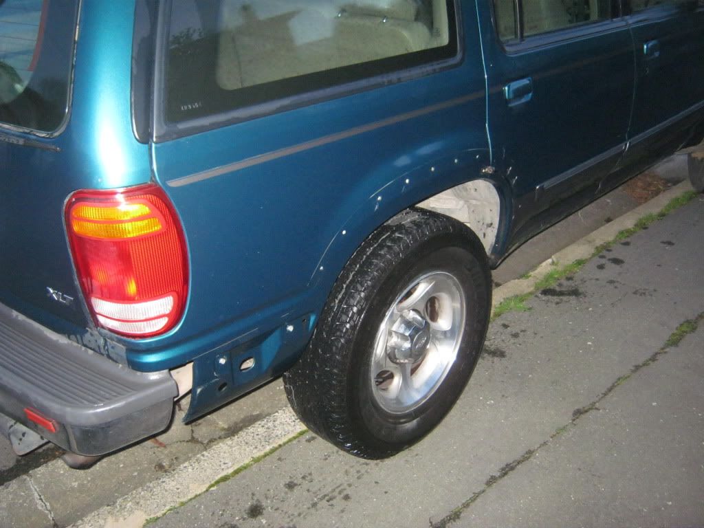
I'm building replacement 3.3 and 4.1 liter engine blocks for use with Mikes alloy head. At present, I'm fitting a version of it to my 1997 Ford Explorer.

The purpose of this post is always to show how our old log head engines can be used in the 21st century. In my case, as an Australasian from New Zealand, I use the engines from 1970 to 1992 Australian Fords, and these are the 200/250/3.3/4.1 blocks, which either cross flow or non crossflow. They are tall deck 9.38" engines whioch were made in Geelong

The long term reason for the XPLOED project is to eventually create a street legal replacement engine for any 1960 on wards X-shell or S-shell Ford. To explain....What is internally known as X-shells are the coil over spindle XK 2000 platfrom cars like Falcons, Futuras, Fairlanes, Torinos, Cometes, Cougars Mustangs etc which aren't Fox chassis vehciles. These were made from October 1959 as 144 cubic inch Falcons, and until Octbober 1980 as Ford Granada/ Monarch's with 3.3, 4.1, 4.9 and 5.8 engines. In Australia, the platform continued in parallel using the XK internal reference from 1961 until 1988 as a XF Falcon/Fairmont/Fairlane/LTD sedan, and then till about 1999 as the XH Falcon utility (unibodyt pickup called a ute).

The S-shell is the Modifed MacPherson strut Fox Mustang/Capri/Cougar/Granada/LTD which weren't Panther or Mustang II or coil over spindle X-shells. They first came out on the 1978 Fairmont and technically continued through as long wheel base Lincoln LSC's till the early 90's and then ended up as the last SN95 in late 2004.

Collectively, excluding the scrapage rate, that could be about 10 million potential 3.3 or 4.1 donars.
 
The XPLOED project has two specific aims.

First is to provide food for my family. Since 1993, I've used Road Roughness vehicles for on site construction quality assurance for laboratories and contractors, local authorites, consultants and in some cases as independent verfication for Government funding. My first vehcile was a 1992 GM Holden Commodore Wagson with a 167 hp Buick V6 and THM 700. I helped in doing 120 000 miles in that car by the time I left the Testing Lab in May 2000. After that,I've used non turbo and turbo 3 liter Toyota HiLuxes to do roughness testing and highway auditing(2002 and 2009 models). That has consumed about 15 000 miles per year every year since 2000. Since mid 2010, I've been independent as XEC Ltd, and doing a similar amount of work using two 165 hp EFI RAV4 5-door 4WD SUV's. That puts me in the seat doing 20% of the South Island state highway network, making me a Toyota driver on and off duty since 2003. I've had to turn down other development work on 3.3 and 4.1 liter engine packages since then, including automatic transmissions and induction kits, as Ive been working over 70 hours a week. As a Ford guy, that made life a little tough. This is why I've started getting the Explorer project up an running.

My second aim for this project is to ensure I do Build Own Operate Transfer developement work on 3.3 and 4.1 engines in the course of my normal duties on the highway inspection regime. Hence my focus is on making sure I exclusively branch out into the non crossflow world which includes ITZOLD, my personal 3.3 Mustang, and XPLOED, my 4.1 engined work Explorer. Since Civil engineering and mechnanical automotive engineering development have similar testing disciplines, I able to do these tasks at the same time.
 
The 4.1 Ford Explorer. Why?

In New Zealand and Australia, Ford imported many Explorer XL and XLTs and Limited from 1997 on. Options included the SOHC and 5speed auto, and sales were good. Many abound, with most owners getting a really great run out of them.It's simple chassis and 8.8 inch diff and Dana ifs make the SUV a great item for taking a gaggle of kids all over the antipodes. Often, though, the 205 HP XLT SOHC got a real hard life, with no timing chain or transmission service, and as a consequence, the scrapage rate through engine and gearbox failure has been high. So there exists a need for kit which eliminates the extra service of the Cologne V6 and Bordeux 5-speed.

My kit allows for an earlier 1984 Aussie Falcon 4.1 engine block to be bolted up to a 1997 Explorer. It uses a 1970 log cylinder head, 6.06" AU 4.0 conrods, a special ultra small 138 tooth explosion proof flexplate to fit the 4.1 engine to the 4.0 v6 transmission using the stock starter motor. The exhast uses the stock twin cat exhast header tubes from the Cologne V6 with a few changes, and the EEC 5 Module remains but in cohoots with an exhilary EA Falcon Throttle body injection computer. Igntion is the Explorer EDIS modified to work as per the later iNTEC OHC 4.0 system found in the 1998 on wards AU Falcon.

The OHV six compact and has a simple sump and starter motor positions which lend it to the Explorer as an engine swap. The engine in stock form as a cross flow yields 131hp net as a 2-bbl and 149 to 162hp net as an EFI. The 1971 Falcon 250 head makes 155 hp gross, which is a bout 133 hp net. I've used stock 23 cc pistons with the non crossflow head, and just added three EA Falcon CFI 'carbs'. These are the common VG30 Nissan Navara/Pathfinder throttle body injection carbs whihc employ the Geo/Chrysler/FordTempo 2.3 cfi style injector which varies flow rate with resistance. It's totally different to the CFI units used in US 3.8 and 5.0 Fox body Fords. Exhast is a dual branch conversion to the stock pre 1970 Ford exhast header.

In my first incaration, the engine has the X-flow cam swapped out for the 1966/1971 spec Ford six cam, which is 256 degrees with about 394 thou lift. Total hp with the mods is likely to be halfway between the 97 Ford Explorer OHV and the SOHC...about 185 HP. Torque will be the same as the SOHC, but the 1250 ib-ft will happen at 1800 rather than 3000 rpm as it is in the XLT.


I'll post picture soon


The reason for the combination is that it uses seven (7) adaptors to link everything, and if it can be fitted in a 1997 Explorer, it can possibly fit an 84 Bronco II.
 
STEVEN.":1ngd928z said:
Ford-6 just wasn't the same without Him ;) :thanks: :nod: . ~Steph/OO6.
That's for sure, and just where have YOU been hiding, Miss 006? Welcome back to both of you!
:D :nod: (y)
Joe
 
Hello,Joe. I was away from Ford-6 mainly bacause I have'nt done anything(performance-wise...)to any of my Ford 6's AND my old Dell Comp FINALLY bit the dust. I didin't get a replacement right away,it took me awhile for me to find the right Comp at the right price.....in the end,I got myself a new HP-2010I. Works great,no problems and now I'm back here again :) . ~Steph/OO6.
 
140272193.jpg
140271844.jpg

140272017.jpg
140272327.jpg

140272482.jpg
140273080.jpg

140273280.jpg
140273497.jpg


Actually, my first modification (A001) will most likey be replacement of those huge way-too-tall side wall flexing 255/70 16 tires with the same 235/60 16 tires and wheel combo I use on my RAV4. Each year Ford kept going up in tire section size. In 1996, the XLT had 235/75 15's. In 1999, XLT's got 255/70 16.

That will hunker the vehicle down and use the same Pirelli Scorpion ATX tires and wheels as I run on my wifes RAV4. They run huge 16x 6.5 JJ alloy rims and require gaurd flares to suit the pip squeek unibody frame anyway.


Lookes like lots of SUV's end up in roll overs, so I may even lower it further (A002)


I notice a few folks tend to shove Mustang Cobra rims on their Explorers. The later Foxstangs and RAV4's and Explorers all share the same 5 on 4.5" stud pitch centre, so I'm going to put altered polished and custom centred RAV4 rims and 245/45 16's on my Mustang when it goes 5 stud next inspection. Basically, the rims are a good size and the Explorer will be used on narrow gravel roads and sealed roads, and the flares get in the way of the rear vision mirror mounted camera gear I use.Once a proper centre cap is made, this means all my vehicles will use the same wheels and similar sized tires

I'm then able to ditch the gaurd flares first so it looks like the base 96 Explorer like this (A003),

http://upload.wikimedia.org/wikipedia/c ... plorer.jpg


and then hopefully the sill flares can be removed like you see on the early Explorers(A004).

http://upload.wikimedia.org/wikipedia/c ... _Bauer.jpg

Then I've got to use my other camera mounts as per another Explorer forums Explorer Sport air snorkel(A005)

http://www.explorerforum.com/forums/sho ... hp?t=74018

Then I'll start on (A006) the Inline six adaption
 
STEVEN.":cdfl5oqc said:
Hello,Joe. I was away from Ford-6 mainly bacause I have'nt done anything(performance-wise...)to any of my Ford 6's AND my old Dell Comp FINALLY bit the dust. I didin't get a replacement right away,it took me awhile for me to find the right Comp at the right price.....in the end,I got myself a new HP-2010I. Works great,no problems and now I'm back here again :) . ~Steph/OO6.
(y) Hope to see you around! :D
Joe
 
Started on my roughness meter today. I'm using two sprag clutched cut-out wheels to measure bump amplitude on the left and right side of the vehicle. As it drives along, the one way clutch on two bike hubs read the bump profile. It fits to the rear suspension of my Explorer, RAV4, and Mustang.

It measures side thrust, lateral acceleration, average angle of the vehicle to the horizontal every 65.6 feet.

It uses two of these data loggers for soaking up the info.


Distance is measured off the Vechicle speed sensor to a British Brantz meter. The movement of the vehicle is co-ordinated with three Canon A495 cameras, which are air operated to capture road defects and features which are points of interest for the contractor, consultant, client or bill payer. One camera sits in the back with a 13 by 13 by 31 aluminum box made of the same plate I make my transmission adaptors from. The box holds a stand alone lead acid battery, the two sprag clutch/cut-out wheels. The box is pressurised by a water cooled Ford Cortina six heater unit in the Explorer and RAV4 and Mustang, which requires the seats to be folded down on the last two.

The camera picks up an AVI file of a ball bank meter (side thrust gauge) and the left and right wheel paths bump readings. On the RAV4, they are independent readings. On the Mustang and Explorer, they are linked by a live axle, so they are not really independent.

Each vehicle has a similar track width, but each is calibrated against one common base. So I can measure road roughness anywhere, and relate it back to an international ride number calibrated by a world class lazer profilometer which I paid to do five runs on four different surfaces back in November 2010
 
You are developing that to manufacture and sell, yes? Good luck on it, Deano, so you can get that seventy hours a week down to a happier figure!
 
In answering your questions, I'll take you through it simply.

My first was a proprietry VP Holden Commodore Executive station wagon with a GM 3800 engine,THM 700, PS, cruise control, 3.08:1 diff and Koni shocks

http://upload.wikimedia.org/wikipedia/c ... ore_02.jpg

I operated that for a consulting engineering firm from 1994 to 2000, but I was learning, and I never was sole charge over the calibration. I was shown a large amount of really good mathematic techniques, and went through the whole calibration process each year. Very good background to have

I made 'my' first one, a single bump integrator Mays meter, in October 2002 with a contracting company.


It's been replaced by a later incarnation just before I left in July 2009, and the new one uses much improved systems and is not related to the one above. Since there is a five year statue of limitations, I'm free to talk about it without hurting my former company at all.

The
XPLODE,
XCTASY and
ITZOLD will be my second scratch built item,

since the unit is able to be transferred between each. Commmercially, its too dificult to sell as a calibrated item unless a well monied company can invest about 6 grand every six months on making sure the item is within normal limits. I was lucky with my first and second roughness vehicles that the donkey work was done with experienced and good engineering technicians. It's doable as a sale item, but not a piece of cake to do. Other New Zealanders (DCL) have made them, but since you'd have to cater for the buyer via professional endemnity, it won't be me.


It's calibrated against an industry standard ISO compliant laser profilometer, which drives an assortment of roads, and then gives you a benchmark calibration to hang your devices numbers off.

Your supposed to end up with a fairly steppless calibration for differnent speeds with respect to different bump amplitudes.
 
Items A001 to A006 have been shelved for a few months while I get my bill paying Road Roughness machine working. That is after all why I do road inspections...to feed my family and maybee ern a little money in the process.

I have to build task R, my Road Roughness unit which houses two 12" cycle cassettes linked to two steel tendons to the left and right axle tube Explorer/Mustang) or the lower links (RAV 4). It measures up ward movement in 1 mm steps via a 300 tooth special cut-out wheel. A very rough example of what I'm doing here


Its basically an 13 by 13 by 31 alloy plate box which holds each cut-out wheel, and that requires a tricky bit of kit...a steppless sprag clutch. He he, I like the box dimensions. "He asked for a 13 but he got a 31..."

My task for today is R001, and that has been to get shop diagrams for my machinist to make some steppless sprag clutches for my Road Roughness meter.


Somehow he's gotta use the inner sleave to remove the 16 degree 'click' found in the bike hubs I bought. The Timken FC20 bearing is able to be held in the sleaved section of the outer Shimano free hub, while the steel inner sleave has to be cut with the same left hand thread so it imparts motion to the outer hub when its rotating clockwise. The 1/4" bearings remain, but the free clutch is totally gutted so a non back-out roller bearing can ensure it only turns in one direction.

I'm sort of doing a Zipp or Winners stepless Freehub for a tenth the price...

 
Well, had to ditch the bicycle hub.

Typical in a supplier industry, when requested to do a job with due notice and consultation, suddenly a no response. I'm a little mad as my proposed supplier bailed on the machining because the free hub was hardened, and it would cost too much time for him in tooling without an assurance that the result would be any good. I'd briefed him over all the details a year in advance, and spent time working on suppling samples and equipment to assist in a postive machining out come, but hey, thats his decision, and I've gotta move forward now.

So I've taken over all the machining myself, and am reworking my measuring wheel to fit the FC20 spragg clutch with nylon inner parts expoxied into the steel parts.

Additionally, I've widened the measurement platfrom from 19.5 inches on the axle, to 33.5 inches, which co-incides with the Fox Mustang inspection plugs for the rear chassis rails. The wire then links to the Fox cars lower shock mount. On the Explorer and RAV4, they will end up with the same centres, which has made it easier to fit the left and right tendon (wire) .

I've eliminated the covering case for the interim, and am using the metric measuring wheel display for bump amplitude. The readings will be picked up by two Canon A495 cameras, and recorded and matched with the Campbell Scientific csv files. The wheel will have a stainless plate of 13" diameter over it, with a reluctor ring for my Honeywell sensor to measure digital counts of upwards wheel movement.

The Explorer unit will be solid mounted to the separate chassis channels, with two 3/4" by 4 by 8 aluminum plinths to hold the measuring wheels. That will eliminate picking up the body to suspension flex all separte chassis vehicles have.

RAV 4 has just enough cargo width to use 33.5" centres between left and right wheels.


Exploder has plenty of room to mount the two wheels, but the plinth that holds the roughness meters has to be grounded on the frame, not the body. The next six pictures show a 37.75 inch chassis spacing, and holes at 33.5" again. I'll drill new ones right over the axle. The plinth extends 38" total


My Mustang has a makeshift dual exhast which kinda obscures stuff. However, it has a set of 33.5" holes right above the shockies, and its perfect for my unifit road roughness meter


The wheel has a wire (tendon) draped over it in service, like a Japanese throttle spindle. It must read only the upward rebound stroke movement, and the FC20 bearing operates as a spragg clutch to turn the green wheel only in one direction. The meter reads total upward movement in meters.

 
As you may be aware, in an effort to lower and make my ride safer for windey New Zealand sealed and unsealed roads, I've de-flared my Explorer of its F57D 7820408-CB Export flares. I'm saving up for some new smaller but lower profile 235/60 16's to replace the 255/70 16's. Static loaded height for new tire is 26.31" vs 29.18"

I was suprised that Saleen in their XP6 and XP8 Explorers lowered the 98 models 2 inches via torsion rod and rear leaf spring reset. Just like I plan to. My whole car will end up being a massive 3.94" lower when the 2.87" lower tire is taken into account. I'll lower it 2.50", and will likely use the stock Saleen Bilstens.
]
 
To calibrate the suspension of the three road roughness gear configuartions I use, and reduce the cost of travel, I'm digging out my concrete garage 51 inches to allow two Explorer IFS units to sit below the floor. They are mounted upside down with hydraulic cylinders to generate bumps the same as those measured from my four calibration sites, or indeed, any measured test at all.

Modular distance is the standard 58.5" track, with a 2" buffer around the nominal 265 section tires it will use.14.4" wide. Wheelbase modules range from 88 to 126 inches. That means my RAV4, Fox Mustang and Exploder will fit, and be able to be calibrated from annual International Ride Index (IRI) lazer profilometer runs I pay for. The vehicle will be secured via a trailer hitch and front chassis iron cleates on each vehcile, with one suspension unit moved forwards of backwards to suit the wheel base.

Tires will be bumped up to 45 psi, and the spin off is that the ABS circuit can be used for road load generation for my ITZOLD 6-BBL carb project, bascially making a defacto dyno. So I can estimate CO2 emmissions with my Sun engine analyser, and also keep things going with my engine side of the business.

Build, Own, Operate, Transfer means that each engine is actually owned by me for personal use, and then sold, so it removes some restrictions relating to testing vheicle for hire an reward in an urban enviroment.
 
My son and I are now doing the off road trial of the grading schedule, a highly calibrated version of the Canadian Optigrade system. Its being hooked up into our Explorer (XPLODE).

As stated in the other post, we are trailing two applications

My son and I have completed ITZOLD Mustang road roughness measurement equipment, and were now trailing the Street Bump and Seizmograph Apps for calibrating against our 10 International Ride Index (laser profilometer) calibrated sites. This allows us to calibrate suspension spring and damper rates to improve ride verses handling.

The two apps we are using are:-

Atrius Seismograph at http://www.androidapps-home.com/seismog ... 57151.html
And the apha program Street Bump at http://www.appbrain.com/app/street-bump-(alpha)/com.citizapps.streetbump

If anyone is interested in hooking up some calibrated equipement into their car, contact me via PM.


We are now off doing the off road trial of the grading schedule, a highly calibrated version of the Canadian Optigrade system. Its being hooked up into our Explorer (XPLODE)[/quote]
 
How others copy your idea......


http://www.slideshare.net/LarsForslf/ro ... 5-36340979

https://www.youtube.com/watch?v=DepfvKMRZ3w


No different from Street Bumps Andriod App and the Seizmograph.

viewtopic.php?f=5&t=64609

xctasy":xp5qa7nc said:
My son and I have completed ITZOLD Mustang road roughness measurement equipment, and were now trailing the Street Bump and Seizmograph Apps for calibrating against our 10 International Ride Index (laser profilometer) calibrated sites. This allows us to calibrate suspension spring and damper rates to improve ride verses handling.

The two apps we are using are:-

Atrius Seismograph at http://www.androidapps-home.com/seismog ... 57151.html
And the apha program Street Bump at http://www.appbrain.com/app/street-bump-(alpha)/com.citizapps.streetbump


If anyone is interested in hooking up some calibrated equipement into their car, contact me via PM.


We are now off doing the off road trial of the grading schedule, a highly calibrated version of the Canadian Optigrade system. Its being hooked up into our Explorer (XPLODE)


A stated, the Street Bump application covered the basics of X, Y Z axis data harvesting.

What is interesting is the use of the inertial Steadying function from the video function.

Anyone like me, who has a compartiviely rough riding car, can see how YouTube uses this smoothening function to right line a bouncy photo. Well, you don't need to be a rocket scientist to figure that the amount of smoothening from frame to frame is proportional to the amount of pitch, yaw and bounce the camera or smart phone was subject to.

th_Clarkes%20to%20Middlemarch%20RWDS%202012%20343_Raw%20verses%20Rectified1.jpg
th_Clarkes%20to%20Middlemarch%20RWDS%202012%20343_Raw%20verses%20Rectified2.jpg

th_Clarkes%20to%20Middlemarch%20RWDS%202012%20343_Raw%20verses%20Rectified3.jpg
th_Clarkes%20to%20Middlemarch%20RWDS%202012%20343_Raw%20verses%20Rectified4.jpg


In the situation above, I drove a road with my Road Rougness meter polling, and my camera running. The Bottom frame unrectified image has bounced 44% off its established flight path, 106 Pixels verses the Top frames rectified 47 pixels. That means an inertial bump has occured, and the compensator has tried to shift the frame. How big that 'bump' was depends on tire type, size, daimeter, suspension compliance, spring rates, dampening and vehicle load, but if you can calibrate the cars suspension against the road, you can then define the size of the bumps in the road in inches by just the camera frame departure.


When calibrated against a known vehicle and road tyeps, this means any compensated camera or smart phone with a compensator can operate as...a very cheap road roughness meter!

Street Bump in Boston was the first...everyone else is trying to copy the excellence of that application to do more road analysis.
 
Back
Top