Ok so here you go step by step details for the DSII distributor wiring hookup when using a GM HEI Module for the trigger.
1. The Orange wire goes to the module pin W.
2. The Purple wire goes to the module pin G.
3. The Black wire goes to one of the modules mounting screws to ground it, is a good idea to also run another wire to ground the module to the body or the chassis. The Module must be grounded properly to work.
4. From the ignition switch a new wire to by passing the old resistor wire (Pink). This is so that with the ignition switch when in the run position is supplying a full 12 volts to the + (Positive) terminal of the coil.
5. From the coil + terminal also run a new wire to the B pin on the module.
6. From the C pin on the module run a new wire to the - (Negative) terminal of the coil.
7. If you have a Tach hook it up to the - terminal on the coil.
8. Unhook the Brown wire from the I terminal of the starter solenoid and tape the wire end.
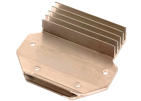
9. Check on the back of the GM Module there are two pins that will need to be removed or filed down so it will set flat and transfer heat. Make or buy an Alum. Heat sink min. of 3/16 inch, thicker is better. Apply the special grease to the back of the GM Module, you can also use a good Computer Heat Sink grease if you want. Mount the heat sink were it will be or stay cool the cooler it stays the longer it will last.
10 Optional wiring you can use a relay and wire direct from the battery or from the starter solenoid (battery cable side) to the relay.
11. The output of the relay will supply full power to the HEI Moduel B pin and + (Positive) of the coil terminal.
12. You then can use the existing ignition wire (Pink) to operate the relay (to trigger it).
13. All the rest of the wiring routing is the same as above. Good luck

 Yes more then likely the DSII will need to have a custom curve for your engine combo to reach its full potential, but first off is your distributor in good condition? I.e. The shaft bushings are not worn excessively and other parts are good usable condition. I have not heard of switching the wires but then that article was a bit generic to cover basics of using an HEI Moduel with many other brands of Electronic Distributors, the above posted step by step instructions are specific to a DSII used with an HEI mod. It's hard to help you diagnose what your problem may be without all the details of your combo of parts as well as seeing it run or atleast a video. Before assuming that it's related to the distributor are you certain that the carb is setup and adjusted properly? Did it run good before you did the DSII swap? Good luck
