DON
Well-known member
I am starting a new thread so I am not stepping on another post. This info was posted:
VIP
Subscriber
Supporter 2022
Supporter 2021
Supporter 2023
To calculate intake valve close point: Camshaft advertised duration (gross duration, not .050") divided by two. Add the Lobe Separation Angle. Subtract 180. This is the intake closing point after Bottom Dead Center on the compression stroke with a cam that is not advanced or retarded. Sense compression doesn't start until the valve is (nearly) closed, this calculation is critical to determine grade of fuel needed, etc. . Actual running compression is determined by the camshaft, the static compression is only a build foundation to match the cam selected. The more mild the cam, the higher the compression ratio and fuel grade required will be for a given Static Compression.
Example of finding IVCP: Cam specs say duration is 205*/260* intake duration, the LSA (Lobe Separation Angle) is 110*
260* divided by 2 = 130. 130+110(LSA)= 240. 240-180= 60 The intake valve on this cam closes @ 60* ABDC. This is with the cam straight-up. Most cams are ground with 4* advance built into the grind. The advance/retard is added/subtracted from this final closing point number. If the cam is advanced, subtract the *'s of advance from the total, if it's retarded, add the *'s of retard to the total.
From the example above: if this cam is advanced 4*the IVC point is 60-4=56* ABDC. If it is retarded 4* the IVCP is 60+4=64* ABDC Insert this final number in the last line of the calculator.
Ideally, the build plan begins with the camshaft chosen, and the target DCR known. Then work backward to determine the piston dish, piston compression height, and head volume. The UEM Calculator is the foundation for deciding what parts are going to produce a matched build- when starting with the camshaft, and the intake valve closing point.
End of post
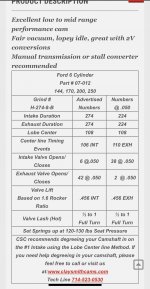
I started by figuring intake opening point and the formula asks for lobe separation angle. My cam sheet gives lobe center but not separation. There must be a way to figure it? It is math
Frank
2K+
VIP
Subscriber
Supporter 2022
Supporter 2021
Supporter 2023
I don't know the rod length of the small 6's, but someone on here does, and I'm sure it's posted somewhere.I haven’t calculated dynamic ever.
my static is about 10.2
What is stock rod by length and how is it measured?
How would you figure intake closing?

To calculate intake valve close point: Camshaft advertised duration (gross duration, not .050") divided by two. Add the Lobe Separation Angle. Subtract 180. This is the intake closing point after Bottom Dead Center on the compression stroke with a cam that is not advanced or retarded. Sense compression doesn't start until the valve is (nearly) closed, this calculation is critical to determine grade of fuel needed, etc. . Actual running compression is determined by the camshaft, the static compression is only a build foundation to match the cam selected. The more mild the cam, the higher the compression ratio and fuel grade required will be for a given Static Compression.
Example of finding IVCP: Cam specs say duration is 205*/260* intake duration, the LSA (Lobe Separation Angle) is 110*
260* divided by 2 = 130. 130+110(LSA)= 240. 240-180= 60 The intake valve on this cam closes @ 60* ABDC. This is with the cam straight-up. Most cams are ground with 4* advance built into the grind. The advance/retard is added/subtracted from this final closing point number. If the cam is advanced, subtract the *'s of advance from the total, if it's retarded, add the *'s of retard to the total.
From the example above: if this cam is advanced 4*the IVC point is 60-4=56* ABDC. If it is retarded 4* the IVCP is 60+4=64* ABDC Insert this final number in the last line of the calculator.
Ideally, the build plan begins with the camshaft chosen, and the target DCR known. Then work backward to determine the piston dish, piston compression height, and head volume. The UEM Calculator is the foundation for deciding what parts are going to produce a matched build- when starting with the camshaft, and the intake valve closing point.
End of post
I started by figuring intake opening point and the formula asks for lobe separation angle. My cam sheet gives lobe center but not separation. There must be a way to figure it? It is math
")