Minimum quench area?

CobraSix

2K+
VIP
Well, I was looking at oddball piston/conrod combos for my xflow.

One combination seems really close, but would result in the position of the piston to be .016" higher than a standard set up would. To determine this, the measurements I used were the listed conrod length and the compression height of the piston (from the center of the wrist pin to the top of the piston).

Is .016" too much or insignificant (assuming non-decked block) for quench area?

This will obviously raise the compression ratio some, right?
 
Don't know the number - low side or high side for squench height. BUT for a guestimatation consider the end all be all rule of thumb in engine mods. Zero decking block to piston the sguench height is equal to the thickness of the compressed head gasket. If the piston at TDC is down from the top of the block that measurement is added to the thickness of the compressed head gasket to arrive at squench height.
 
Howdy Slade:

You will need some additional measurements to know where you are at with this piston. 1st, what is the current deck height of the engine- that is from the top of the stock piston to the block deck? If it is a typical .025" of most 200, an additional .016" of pin height will not be a problem of physical space. The new deck height will be aproximately .009" with the new poston. CR will increase by aproximately one and a half tenths. It it was 8:1 it will become 8.25:1.

The other factor that needs consideration is the head gasket thickness. If it is a typical aftermarket composite gasket, deck clearance will be in the .050" - .060". Still way too much to optimize the quench effect. Ideally, a deck clearance goal of .035" is optimum. So my next question is- what is your goal in exploring this piston?

Adios, David
 
Well, here is what I was looking at.

I have a 250 Xflow in my garage. I'll start tearing it down next week or so. But the standard bore is 3.68". At this point, I'm unsure of the deck to piston height yet since I haven't torn the engine apart yet to check if it's been machined.

So, what I'm looking at is this:

The 4.6L engine has an overbore kit from Manley that uses pistons for a 3.70" bore. So my thought was about using those pistons. A complete set of forged pistons for that is around $500, with 2 spare pistons for the 6 (comes in a set of 8 ). The compression height was 1.21" vice the 1.51" for stock 250 & Xflow pistons. From there, my plan was to use C9 rods with a length of 6.20". This would bring the stroke to rod ratio up, which from what I understand is better for the engine. Additionally, the 4.6L pistons have a 1.2mm pin offset, which again reduces side loads on the engine.

Downside, the wrist pin for the 4.6L pistons is 22mm, where the C9 rods use an ~23.54mm pin. So, I figured the pistons would need to be bored out some to allow for the larger wrist pins.

The rod journal diameter on the C9 I think is 2.10" and the stock crank is 2.1236" (I think, but will verify when I open the engine up). So again, a bore would be required on the rod end, but the forged rods aren't too pricey.

Granted, this will get pricey due to the machining required.

I'm just on the cusp about what to do with engine selection. Part of me wants to be a Turbo Xflow to get around 250 RWHP, so some of this may be overkill. But I figure if I build the block to hold the power, I can go over my goal. But the money involved makes getting a V8 oh so tempting. I have an explorer near me for sale, a 1997, with a running 5.0 that came stock the the GT40 heads, for $600. After pulling the engine, I could probably get all the money out from parting the body.

I don't mind spending money on building a solid xflow...just trying to figure out a direction. Need to talk to my local engine builder this weekend, see what he says about some of these costs.
 
Downside, the wrist pin for the 4.6L pistons is 22mm, where the C9 rods use an ~23.54mm pin. So, I figured the pistons would need to be bored out some to allow for the larger wrist pins.

You could have the C9 rods small end bushed and machined to fit those 22mm pins and this also equalizes the rod lengths during rebuilding. Little custom crank regrinding should take care of the big ends too. :nod:
 
Howdy Back Slade and all:

"The rod journal diameter on the C9 I think is 2.10" and the stock crank is 2.1236" (I think, but will verify when I open the engine up). So again, a bore would be required on the rod end, but the forged rods aren't too pricey."

The miss match between the rod big ends and the crank journals opens the possibility of off-set grinding the crank journals. From your measurements it would take an offset grind of .0236", which would increase stroke .0472" and reduce deck height .0236". That may take care of the need to deck the block anymore than the minimum necessary (assuming a factory deck height of the typical .025" in most 200s) to true the mating surface. Just a thought.

I'll be anxious to hear the actual measurements once the head is off.

Adios, David
 
Well, I started looking into other possibilities yesterday afternoon. Custom Billet Con Rods. Would run $1100 for a set of 6. This way, I can have the wrist pin journal bored to the correct size to match the piston, the big end machined to the 250 con rod dimensions, and make the length what I need. Granted not cheap, but forged 4.6L pistons are only $500, so that evens a little bit over forged 250 pistons at $800 here in the US. Plus, I think by the time I have pistons and rods machined, include their original purchase price, I'd end up spending more than just going custom. Granted, billet isn't as strong as forged due to grain patterns, but it'll hold up better than cast, if only by a little bit.

But it kind of goes back to the original question though...how much is ideal? From some of the reading, 0 deck-piston height is ideal for the cooling and flame front properties. Obviously, increase compression, but maybe dealt with by having a larger dish.

Still got to decide how I'm going to deal with this xflow in my garage...
 
CobraSix:

Everything I've read on the subject over the years seems to suggest that .038 to .040 quench is about optimal.
 
Not sure if it is true, but in conversation with my performance engines teacher, he claimed that going zero deck could be a bit more hazardous than having the piston poking out about .005 due to the added weakness point at the lower mating surface.

Optimal quench area has always been .035-.045 depending on what is used for rods, with cast bein larger and forged, smaller in that spectrum due to tendency to stretch.

With your goals, I would take a small portion of your focus off of the budget( while maintaining sanity of course) and put that on correction of the rod stroke ratio issue that is clearly present with the 250. I honestly only suggest this because you have a firm goal on hand and many options that are well within the same price group.

I am very interested in your decision and will be keeping up with whatever project this turns into.

Gerald.
 
Establishing a good tight squish might well provide its own answer to the small increase in compression, Cobra, so that the onset of detonation with the new and higher static C.R. is not only no more likely but might even be somewhat reduced. Tight squish is one of the rare win-wins with no trade-offs. I got clued into this when racing alky-burning outboards in the late-'60s.

Since you have to have the head off and the engine apart anyway, why not check the actual squish with clay or soft solder? This would be after you've numbered all the pistons and rods, measured the actual variations in rod length and piston pin-to-crown and crank stroke, and then combined "shorter" rods with "taller" pistons, etc., etc., to even-up the assemblies.

As with a whole lot of other upgrades you can make, tight squish is something the factory engineers would like to have built into engines as they came off the assembly line, but could not because holding such tight tolerances would be unaffordable, with a high scrap-rate. Half-smart people are always saying, "If the factory engineers had wanted it that way, they would have built it that way, so do you know more than the engineers who designed the car, hmmm??" You can try to explain, but they seem to be oblivious to reason.
 
The tighter the better until it hits. Aluminum rods and extreme rpm needs a little extra, steel rods and low speeds can go fairly snug.

I left the pistons sticking .007" above the block on my 300. It will never see more than 4000 rpm (and rarely even close to that).
50,000 miles and no problem.
Joe
 
With a 9.38" deck register, 1.21" pistons and 6.24" rods I use, the pistons stick out +50 thou. A minus(-)16 thou is the ideal quench for Boss302, Boss 351, 351 4V HO Clevelands and stock X-flows. Ideal gasket for each is multi layer composite of about 41 thou. These engines are the worst detonators when the spark, piston ahd heads are poorly matched, but are awesome when matched.

The 4.6 3.700" forged piston is great, they run cooler and you can use factory UA Ford Corsair 2389 cc con rods like I use on my planned FAZER 6Bi (Blowen & Injected) or FAZER 6Ti (Turbo & Injected) engines.

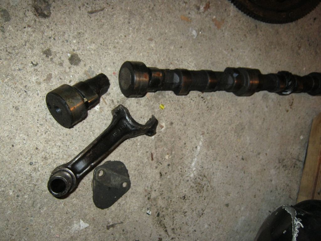
These are ex Nissan 2.4 litre KA24E inline-four conrods. This engine was found in the Australian Nissan Pintara/Ford Corsair pair produced from 1989 to 1992, but found in many other Nissans worldwide up to 2004 (incl Xtrail). It power was a very ordinary nominal 129 hp at 5,600 rpm and 139 ft·lbf at 2,800 rpm, but is the basic 240SX engine, and I wouldn't suggest it unless it was ballistically strong. And they are! They are 300 Ford spec for strength, but have a nice small big end and little end to suit the Ford Modular piston. You have to regrind the crank bearings to suit, but there's nothing in that compared to the cost of, say Astron 80 2.6 6.5" conrods or any number of aftermarket versions.

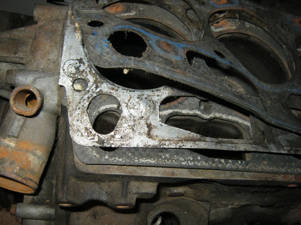
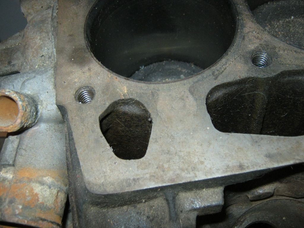
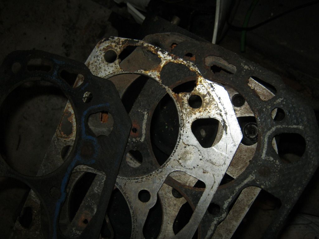
Long ago over here, I removed an AIT Turbo equiped 4.1 headgasket and crank from a blown Fairlane back in 2003 when doing my AOD adaptor trial fit. I showed the rods from that failed combo briefly. The process to get the right quench would be to have an alloy, tin or steel 22 thou thick adaptor made up on a CNC lathe, and use two Permaset 41 thou gaskets. That way you get the right quench. You must ensure the cooling system and those back water holes in the block don't ever rust the intermediate steel/tin/alloy/copper gasket, or it will be trash like that Turbo engine was. Here is its gaskets on my old 1982 X-flow block.


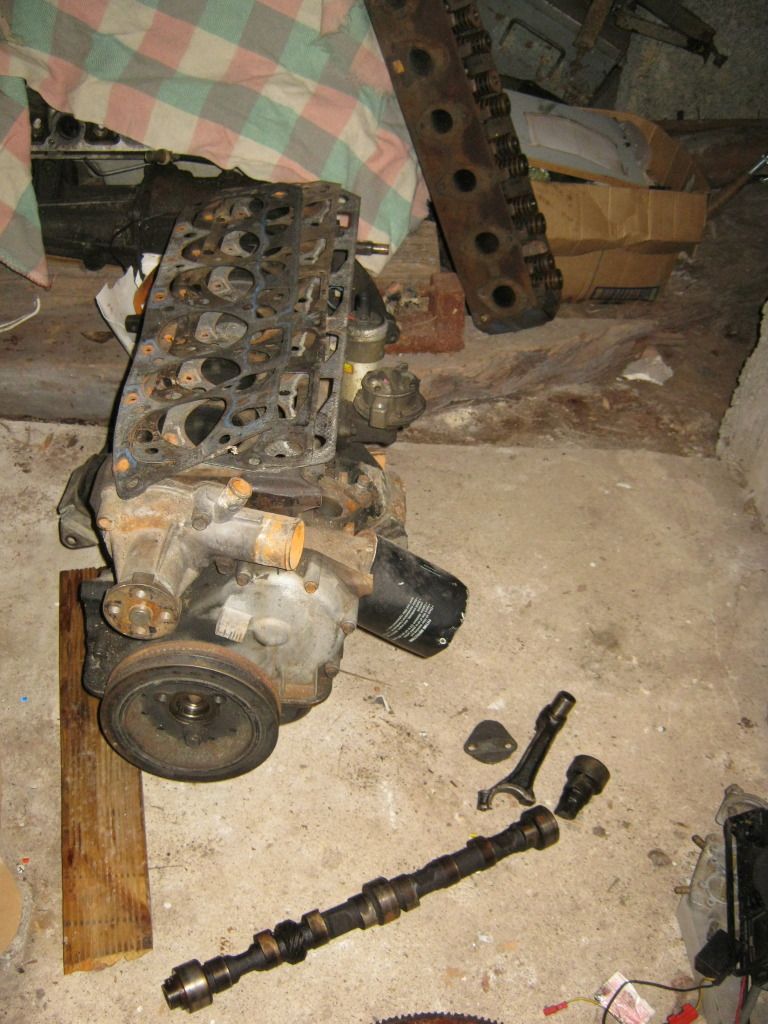
When turboed, here is what can happen to a stock X-flow conrod under load more than 360 hp and 14 pounds of boost. This became an early hot rod Twin cam engine (pun intended).


22 thou plus one extra 41 thou Permaset give you 13 thou quench with a 50 thou above 4.6 piston and KA24E rods. These decompression plates were used on most aftermarket turbo (Mike Vine, AIT, TurboTechnics, Normalaire Garret, Ray Hall) Falcon kits from 1980 to 1987, mainly because Ford varied its combustion chambers lots over the XD, XE and XF run to meet three national and two NSW State emissions standard changes.

Gasoline and those later alloy high swirl heads and an agressive stock TFI spark system can kill your bottom end. Or, if you use a 291 degree cam, EDIS, and good ecu, forged pistons and premum rod bolts with good stock rods to avoid incipinet knock (Georges 10 second TD Cortina has them), it will last a long, long time, even under 25 pounds of boost.
 
Back
Top