moved forums efi tuning ?

A

Anonymous

Guest
:oops: Once again I am humbling myself by posting here. I know alot of you will give me flack for tossing money out the window but it is already gone.
I posted in the 240-300 forum and I got told how my first mistake was going efi, I thought it was calling clifford. So I have this giant pile of money under the hood of my Bronco right now and I'm scared of it.
I really want to get a solid timing curve set up before I spend to much time on fuel. I am thinking that I may lock out the mech. adv. so I can time it all with the computer. Can anyone tell me how this is done before I go ripping apart my dizzy? I've heard you can just weld it.
Also I have a 170amp one wire alternator that I believe is not regulating the voltage like my ecu and ignition wants. Might be up for sale. fits stock brackets
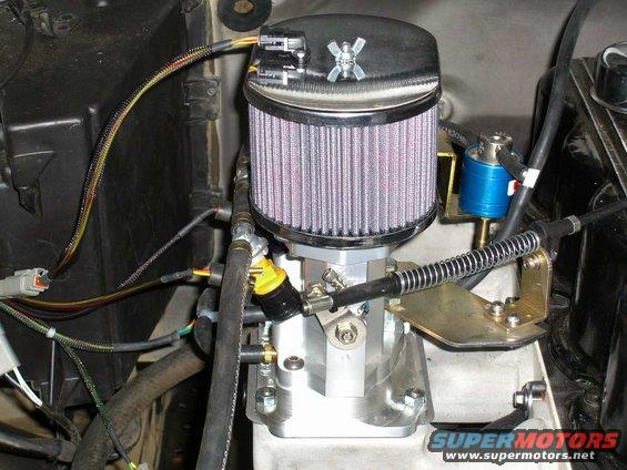
BTW we are talking about the redline efi yes it is installed and running. I must be the first on a 300 cause I sure can't find anyone else willing to talk about anything more than how much it cost.
Please don't tell me to time it by ear. which was the response in my last post. I know there is a wealth of knowledge here, Thanks. I will answer any questions as thoroughly as possible. let me know if I get to long winded.
 
have you thought of putting in a stock TFI ford distributor? they are locked timing and designed for EFI from the get go. or will that not work with the redline EFI? I would start with fuel tables though and put weak timing in it. once the fueling is pretty close then I would bring in a little more timing each time if it needs it.

do you have any pics or more info on your setup? is it using the stock EFI manifold for a 300 or a TBI setup?
 
I am assuming I know which dist. you are refering to. This system has two wire hookup. The dist for efi has a module on the side? It has the clifford intake with tbi. I would love to share pics but not sure how.I'll try to paste a link.

http://www.supermotors.net/vehicles/registry/15046

also it is running cliffords 264 cam, short headers, I am running dual 2" into magnaflow with single 3" out to stock exit behind rear wheel.
I am in the process of getting the fuel roughed in now.
 
dijera":1knyftmv said:
OK I am going to need some help posting pics.

Just right click on the pick and choose "Properties"

copy the photo address - ,jpg

click on Img to open, paste, click again to close
cimg0015.jpg
 
do you have a wiring diagram foir the ECU?

instructions?

I know nothing about it.
 
dijera":yfo6l1kg said:
... I am thinking that I may lock out the mech. adv. so I can time it all with the computer. Can anyone tell me how this is done before I go ripping apart my dizzy? I've heard you can just weld it...

It shouldn't be difficult to weld it in one position although I have never done it. The DS2 is pretty simple though so a simple dismantle ought to show you what needs done. As mentioned above, the TFI distributor has no mechanical advance.
Joe
 
Thanks for posting that pic for me.
I have a manual in pdf format but again don't know how to attach it. The system is really pretty simple. It would make alot more sense though if you could see the screen shots of the tuning software.
I just went out for a drive and got the fuel more in line. kept the timing down but I think I need a better timing light. Was hearing some pinging at low rpm low vac situations. I do have access to a snapon light but only during the week. I had init timing set at apx 12-14 pretty much the last notch on the timing scale probably too much with out the vacume retarding it when I put it down. ?
to summarize how the system works:
-it is a closed loop system but you do the tuning with O2 input off.
-you still see the "a/f" even though it's off, for tuning referance.
-the main sensors it uses are; clt. tmp., air tmp., MAP, O2, tps
-there are two main fuel "curcuits" for tuning basically main and idle
-you also have the basic map for fine tuning which is rpm vs. MAP
-there are two tps maps one is pulse width added for throttle position-
-the other is a percentage of the previous map that is figured in for rpm
-there are maps for clt temp, air temp, and bar enritchmnet
-maps for clt temp, MAP, rpm ign. retard
-there are accel and decel options
-IAC as an add on, I don't have this yet
-and more but thats most of what's going on
-The ecu reads the event @ the dist and computes timing from there
-ecu is wired to - side of coil
One issue I have is seeing everything in different measurements than I'm used to. bar instead of vacume, C. instead of F., lambda instead of A/F
this is from memory. you can pretty much monitor all aspects of the engine while driving, it is really a capable system if you know what you're doing. I don't have schematics but could probably get pin reference

I probably could use the TFI but tech support is limitted from R/W let alone Clifford and I wouldn't know how to wire it up to the ecu. I had a dist. out of an '87 and they couldn't help me so I went back to DS2. I assume that's what you're telling me I have.
I will open up the diz I'm sure it can't be that hard.
 
One thing I have a hard time understanding is how the timing event can be altered electronicaly. I can see how the signal can be delayed but the spark still has to travel through the rotor and cap to be delivered at the right time. I can see how distributorless systems work. I am just not so sure about controling timing this way thruogh a distributor. I could upgrade to a crank sensor system I believe, but that's lots more money and time I'm sure. Can anyone enlighten me on how this works or am I right in assuming that this system is limited in how much you can change timing due to mechanical factors.
 
dijera":15s85k1e said:
ecu is wired to - side of coil

Is that the only wire atached to the - side of the coil?
If so, then the ECU does all the timing work.


If not, then the ECU is only using the - side for a tach reference
 
dijera":2rkifrxi said:
One thing I have a hard time understanding is how the timing event can be altered electronicaly. I can see how the signal can be delayed but the spark still has to travel through the rotor and cap to be delivered at the right time.

Are you talking about rotor-to-cap timing (or phasing)?
Yes, it can be a problem with many engines. Its definitely not a perfect system. Sometimes the rotor is firing before it gets to the cap terminal, sometimes after.
 
That's exactly what I'm talking about. It seems that even though the rotor turns at half the speed of the crank that you would still have only a few degrees window in which the spark can fire through the cap. So how could I theoretically retard spark say 30degs at say 1000 rpm? I mean I know how to enter it into the timing map, but if the rotor is firing after it passes the terminal how does the spark get to the plug wire?
Just trying to increase my knowledge/understanding.[/quote]
 
the same thing can happen in a points ignitin setup or even a durspark. if your rotor is not timed to the points lobs on teh shaft or the reluctor you will get a misfire issue. the key thing is to have your base timing set so that once the timing is changed electronically everything still works correctly.
 
I still don't get it but that's OK for now. I still seem to have a gremlin in the system. I was going to drive it today to go across town. I got her all warmed up went to go down the road and when I put my foot down she falls flat on her face :devilish: . I had been fighting this issue before but thought I had it figured. I found out I was loosing juice through a faulty starter solenoid. When I finally got one that was good she ran great for the first time ever. I tested to see if that had somehow happened again and there appeared to be nothing wrong, there was no power coming through the neg bat cable. One thing I need is to buy a multi meter. I have done all my testing so far with just a light. I still think my alt. may be screwing with things.
 
Make certain that everything is well-grounded. That means to the block, the frame, and the body. Lots of those gremlins are caused by poor grounds.
Joe
 
Lazy JW":3vhobkim said:
Make certain that everything is well-grounded. That means to the block, the frame, and the body. Lots of those gremlins are caused by poor grounds.
Joe

+1

That is worth repeating.
efi HATES bad or questionable grounds.
 
Just to clarify. I have a ground from block to firewall, battery to frame/motormount, then motormount to starter. I assume that the starter ground is considered ground to block. The ecu is run straight to neg. bat. The ecu body is not grounded because the intructions specify not to, but the ecu comes with a grounding wire attached the one of the mounting bolts and in another section of the manual it mentions that it can be used to ground the ecu. Ihave had it both ways and doesn't seem to make a difference. All of my grounding locations have been cleaned with wire wheel/grinder, all new cables. That's been my main focus is trying to find bad ground.
Does the bellhousing starter ground count as having block grounded. Or should I run another straight from frame to actual engine block. I know you can't have to much ground. Maybe I answered my own question.
Thanks for following this thread.
 
I have heard that o2 sensors are alot like spark plugs. Now After my initial start up I had to change my plugs because the thing wouldn't even fire, let alone run. The plugs were totally fauled. Now what I'm thiking is that maybe I'm getting a false lean reading. not all the time but. Maybe I'm adding fuel to try to get rid of this lean reading and just making it worse. Any way to verify this without buyi8ng a new sensor?
 
Back
Top