drag-200stang":3lyglgg1 said:
Bubba,
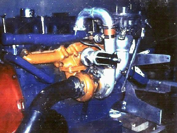
My eyes are OK but, my brain is shot. I can't get photobucket thumbnails to work properly. I'm gonna work on it but, meanwhile you can go to Classic Inlines, Engine Photos under boosted turbo section - there's a larger picture there.
Man, just lost 10 minutes of post update on left hand starter motors in Aussie I6's and Windsor/Romeo and Coyote V8's. It was a tribute to you.
But I X@##$%%

:thumbdown: :fume: :shockin: :splat: was typing to fast to save it cause I had 8 windows open already .
But if you use the quote command, it'll show you two ways of getting the clickable waearble art work to wounderfully explode up a whole bunch by one click. Hope ya like it, bro!
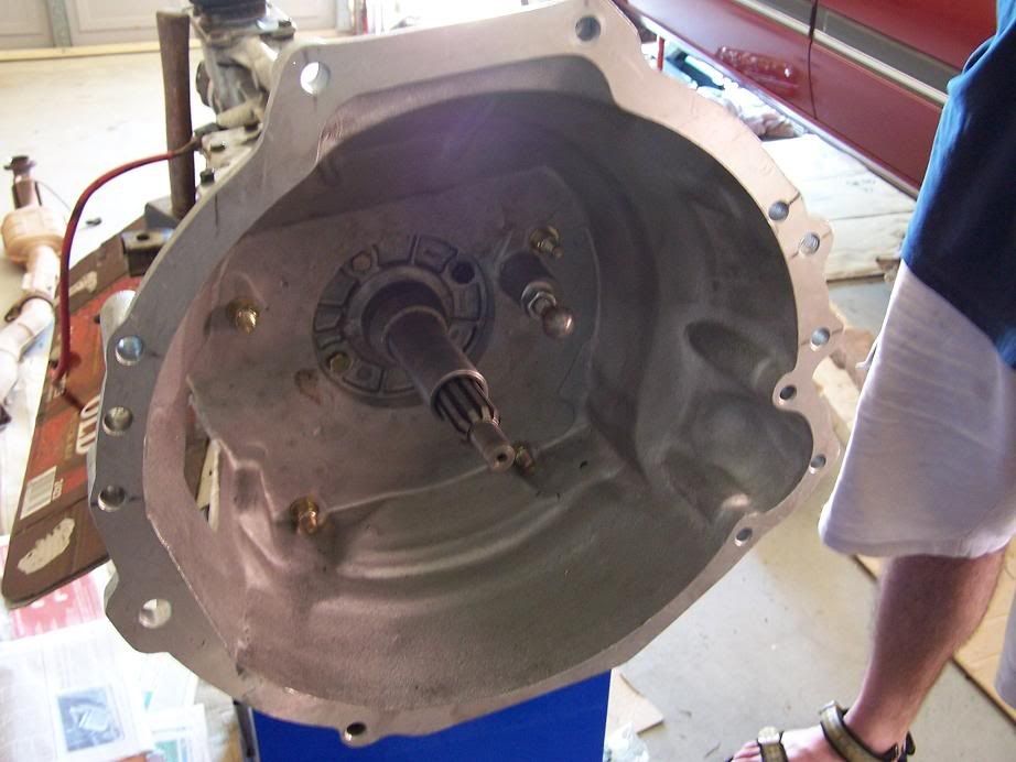
Once the low mount small block Ford 250/300/SBF pattern bell is used, you can copy the 1992 to date V8 left hand starter system. Because the OHC I6 from Dec 1987 pre-production was designed with the AIT turbo in mind, the starter was shifted to the 265 Hemi Chrysler Borg Warner set up by Ford Australia. The American import 5.0 225 HP engine got an Aussie special low mount starter without SBF block mods to suit the Right Hooker Aussie Falcons. Previously, the RHD X-shell (early Mustang based Windsor and Clevelands in a US designed coil over a arm unibody) had the US right hand starters, and had enough space to fit em.
With the Cologne built 2.0 engines, Ford of Europe cast the Hummer trans with two bumps for left or right starter, the Cologne V6 had the left hand starter, and anytime you go to the left hand starter on the I6, you can make an O for Orsome exhast out of the C code 250 or B and X code 200 4.25" four bolt exhast manifolds, and make it good.
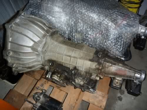
I use all your tricks you used to get a good turbo kit to use the C,B and X code headers my FAZER turbo engines, because you can fit a 4-stage V8 auto gearbox in with a huge turbo with standard factory parts.
AK Millar could have sorted out Fords 2.3 Turbo carb problems. His LPG turbo work on the 71-77 250 and 300 and also the 1981 255 -and Factory Impco W code Carb 2.3 Turbo carb engines followed a lot of his excellent carb adaptor work. Ford could cover off product liablity with his work under those projects, they could cover off the welded three and Four port "horseing around with the mustang six" mods. Ak was a leading light, it remains for Linc's later work on the drag200 stang low mount starter turbo to be fanned into flame...
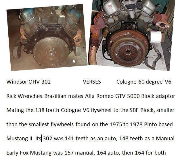
Your 200 engine has all the good features I liked in Ak and Lincs set up. The 425 hp FAZER6Ti covers off all the turbo exhast problems with a factory turbo solution. One Brazillan Cologne V6 bell housing to a SBF block made me see that the Ford Australia already had a factory solution to the I6 Turbo exhast manifold limits.
The best thing any of us can do is learn what people did 5, 10, 15 and 30 years ago, and copy it!
And anothe thing, drag 200stang. In addition to showing us all your excellent turbo set up, your Bosch L jetronic work and photos has solved lots of turbo set up issues.
If you go to Mustang Geezers latest engine upgrade post, we've gone through the clickable big picture method of photo management. Its a swearing inducer first up, but with practice, you'll ler to tollerate it. When you are able to copy a book of my desk with a camera shot, load it to photobucket, and have Chad in America respond with yippee when he links on to it with his i phone, you'll get a huge, massive kick like 14 pounds of boost coming into a 200 cubic inch Ford.
 <>
<>  <>
<>  <>
<>
 <>
<>  <>
<>  <>
<>")