There are numerous pics in Leo Santucci's Chevy 6 Performance Handbook. But extensive brazing to the intake ports and very large intake valves are required to reach those flow numbers....I'll see if I can find some pics to share on here...Is this with or without epoxy/welding? And do you have any links to pics? I'm very curious how they got there
You are using an out of date browser. It may not display this or other websites correctly.
You should upgrade or use an alternative browser.
You should upgrade or use an alternative browser.
U-flow horsepower limitations
- Thread starter Walken100
- Start date
I'm curious. Was this an NA application and do you know the HP? I'm wondering how the engine treats the Siamese ports from an area stand pointreshaping the ports, we were able to achieve a best of 349 CFM on the intake and around 230 CFM on the exhaust.
See Post #39 below.I'm curious. Was this an NA application and do you know the HP?
Outstanding cross post. Thank you! That's a metric crap ton of RPM.... and horsepower.
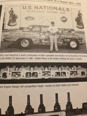
Yes, it was naturally aspirated and the last time I saw it dynoed in the late 80's it made 612 HP. By that time the engine was no longer in our Chevy II and was put into a Comp Eliminator rear engine dragster owned by Brian Browell until around 1988, when Brian wanted to take over the driving chores. After switching from the inline power, he switched to the Chevy V6 PowerPlant and had Grumpy Jenkins do his engines until his passing some years back. Brian still races in Comp Eliminator and is the owner of Browell Titanium Bellhousings currently....I'm curious. Was this an NA application and do you know the HP? I'm wondering how the engine treats the Siamese ports from an area stand point
The dynamic port flow for the three Siamese intake ports is different.I'm wondering how the engine treats the Siamese ports from an area stand point
If you look at the 1 5 3 6 2 4 firing order, the intake timing for cylinders 3 and 4 have a 360 degree interval and there is no overlap between valve openings in the center intake port.
However, cylinders 1 and 2 have a 240 degree and a 480 degree interval as does cylinders 5 and 6.
When you have a drag racing camshaft lobe profile with well over 240 degrees there will be valve overlap during the 240 degree interval in those ports.
Valve timing can be altered slightly between those cam lobes to decrease the overlap period.
CNC-Dude can shed more light on the subject.
Otherwise, you are looking at a large volume intake port that is relying on the port lump to increase air velocity and tapered rectangular intake manifold runners for velocity and ram.
Last edited:
That would explain the high rpm capability...Otherwise, you are looking at a large volume intake port that is relying on the port lump to increase air velocity and tapered rectangular intake manifold runners for velocity and ram.
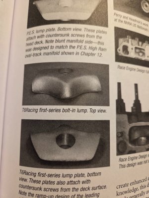
Here are a couple of pics that Wallen asked for. First, not trying to hijack the thread, but to reinforce what Paul was describing in an outside the box manner of thinking to Wallen and to show with creative thinking what can be accomplished. The top Pic shows the stock intake port with the obnoxious bolt bosses impeding air flow. The middle Pic shows after the bosses removed and the port floor filled by furnace brazing to create a short side radius, or lump as Paul mentioned. The last Pic is the 21st century solution which is a bolt-in lump that is simple to install by most any DIY-er with simple basic tools and at a much cheaper cost. However, they only mimic the street version brazed lump head that the late Kay Sissell offered, but still produces between 260-270 CFM, compared to the factory 160-ish port....

Attachments
Last edited:
No need to apologize. My goal is to continue my informal education on cylinder heads and flow. This is a great case study. Thank you.First, not trying to hijack the thread,
Here's what the latest technology is in Super Stock cylinder head porting. It retains the factory port volume per the NHRA rules, but flow is increased tremendously over the OEM port location and shape. You could do the same to the Ford 6 ports...

I have, sorta. I've raised the center of the entry CSA .4". So far the best I can do with out finding water. Note the bottom of the port will be raised by offsetting the intake runner~.3". This got me to 250 CFM. In the hands of a pro I believe this technique would get you close to 260. And yes I have to make an intake manifold.Here's what the latest technology is in Super Stock cylinder head porting. It retains the factory port volume per the NHRA rules, but flow is increased tremendously over the OEM port location and shape. You could do the same to the Ford 6 ports...
View attachment 28229
Link to my progress...
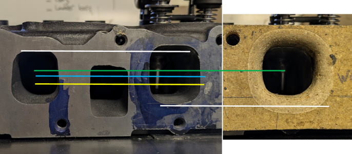
The question I asked myself was how to raise the port without epoxy. After looking at port section pictures I outlined where there was material/opportunity (black lines). Additional background, with flow ball testing I noted extremely fast flow at the roof and limited flow on the floor. So I had a substantial vertical velocity gradient.
View attachment 27949
View attachment 27951
I then realized that the goal is to raise the flow column/cross sectional area as cleanly as possible. Specifically the center of the CSA. Colored lines above approximate the change in the center of the flow path CSA before/after work.
The picture below illustrates the changes in the center of the CSA at the entrance. Yellow is the original center of CSA, Blue is after widening/squaring up the port entry and green is after raising both the roof and the floor. Note the floor is raised using the intake manifold flange and not epoxy (currently). The net effect was to raise the center of the port flow area almost .5"
View attachment 27950
The next picture is the outline of my work.
View attachment 27945
Comments on the picture above,
- The second realization was that I needed a larger entry CSA. if I wasn't trying to push my peak HP to higher RPM I may not have widen the port as much as I did. I likely would have just squared it up.
-And the second point is that the horizontal line just above the floor is the approximate amount that I raised the floor.
- The port shape transitions from the outline at the entry to a more standard shape before the short turn (leaned in at the top).
- I ended up shaping the bottom to match the top. Limited impact to flow but notable impact to stability.
End results:
- An improved vertical velocity gradient, flows at the top slowed down and flows on the floor sped up.
- ~20 CFM improvement
- Rock solid stability (when implemented correctly)
I think I've said this before but I need to emphasize that doing this without a flow bench won't work (in my opinion)
I know, you asked "what time is it" and I told you how to build a clock........
Attachments
Last edited:
Not sure where this info fits into you vault of info, but several aluminum Chevy 6 heads have been produced in the past. They were of the U-Flow design with high port intake port angles. Several have been CNC ported and achieved over 400 CFM on the intake side. One engine with one of these heads currently produces over 1300 HP with a monster turbo on it. So if there is any doubt about the potential of a U-flow head, and that it is inferior to a crossflow design, there are plenty of examples that show otherwise. This cylinder head out performs the best efforts of a comparable Chevy 6 fitted with a top shelf hybrid head created with the best of the best V8 aluminum race heads at the time...
I think its accurate to say that a correctly designed head (u-flow or cross flow) will quickly move the problem to a different area in the 300. If one was looking for 3 hp/CuIn naturally aspirated a cross flow head rises easily to the top. Otherwise it's a trade off in packaging between the two options. This is not to say that I believe an aluminum U-flow head is (or is not) the way to proceed with the 300. And lets not forget the "cool" factor. It's real and there are folks that would pick cross flow head over a U-flow head regardless of performance.Not sure where this info fits into you vault of info, but several aluminum Chevy 6 heads have been produced in the past. They were of the U-Flow design with high port intake port angles. Several have been CNC ported and achieved over 400 CFM on the intake side. One engine with one of these heads currently produces over 1300 HP with a monster turbo on it. So if there is any doubt about the potential of a U-flow head, and that it is inferior to a crossflow design, there are plenty of examples that show otherwise. This cylinder head out performs the best efforts of a comparable Chevy 6 fitted with a top shelf hybrid head created with the best of the best V8 aluminum race heads at the time...
Are any of the Chevy straight 6 heads still offered?
I'm still curious about the pro's and con's of a u-flow head regarding overlap flow.....
I had casting patterns for one up until about 7 or 8 years ago, it was a design similar to the head Sissell Automotive made. I pitched the idea of modifying the patterns to cast a Ford 300 head because the bore spacing was close enough to allow it....but crickets!I think its accurate to say that a correctly designed head (u-flow or cross flow) will quickly move the problem to a different area in the 300. If one was looking for 3 hp/CuIn naturally aspirated a cross flow head rises easily to the top. Otherwise it's a trade off in packaging between the two options. This is not to say that I believe an aluminum U-flow head is (or is not) the way to proceed with the 300. And lets not forget the "cool" factor. It's real and there are folks that would pick cross flow head over a U-flow head regardless of performance.
Are any of the Chevy straight 6 heads still offered?
I'm still curious about the pro's and con's of a u-flow head regarding overlap flow.....
Last edited:
It is mostly about the chamber design.I'm still curious about the pro's and con's of a u-flow head regarding overlap flow.....
One of the best designs is the Ford Boss 429 head and the current Hemi head.
They are a closed hemi chamber design that is centered in the cylinder with equal size quench pads on both sides of the chamber.
This creates a channel between the intake and exhaust valves that are angled towards each other.

Because of the low position of the camshaft and the long pushrods, the 300 six is restricted to a more inline valve design.
The chamber may be able to be twisted slightly and the valves can be canted towards each other.
Last edited:
Thoughts on what helps the stock ford head with overlap flow. I ask because I still haven't finished chambers.....It is mostly about the chamber design.
Sergioziegler
New member
Hi, how are you? I have some videos to share of the work done in Argentina on the Ford Falcon 188/221 ci, very common in the 70s and 80s. It involves cutting and tubing. Greetings from Argentina.

Similar threads
- Replies
- 10
- Views
- 3K
All Small Six
Restrict Oil Feed to Head on high RPM 250?
- Replies
- 11
- Views
- 2K