Hello, I'm still pretty new to this page and have been searching a lot about the megasquirt and it seems that it's the easiest way to tune the 300 EFI. I'm familiar with newer cars (everything is done through OBDII) and older cars, but to be honest I'm pretty much clueless on what to do here. I'd appreciate if somebody could take the time, or direct me where to look to answer my questions like: what do I buy? How do In install? What can I do with it? My truck is a 93 F150 300. My goal is to be able to add a little more fuel more that it's straight piped and has an intake and possibly build the engine and turbo it down the line. Thank you in advance for your time.
You are using an out of date browser. It may not display this or other websites correctly.
You should upgrade or use an alternative browser.
You should upgrade or use an alternative browser.
Megasquirt install questions
- Thread starter Bigshawnnn
- Start date
Bigshawnnn":81xlwlw7 said:Hello, I'm still pretty new to this page and have been searching a lot about the megasquirt and it seems that it's the easiest way to tune the 300 EFI. I'm familiar with newer cars (everything is done through OBDII) and older cars, but to be honest I'm pretty much clueless on what to do here. I'd appreciate if somebody could take the time, or direct me where to look to answer my questions like: what do I buy? How do In install? What can I do with it? My truck is a 93 F150 300. My goal is to be able to add a little more fuel more that it's straight piped and has an intake and possibly build the engine and turbo it down the line. Thank you in advance for your time.
Read up at http://www.msextra.com lots of info and user/support forums. You can read the hardware and software manuals.
https://www.diyautotune.com Has an MS2 based plug and play for Ford EEC-IV Vehicles. That would be batch fire injection (as is EEC-IV) then you would use wasted spark or a distributor ignition.
I want sequential injection and ignition. I considered MS3X, but have purchased the AEM Infinity 308 ECU. I won’t be installing it for a while yet.
There are a number of builds on this site. You may find this is a better way to search viewtopic.php?f=71&t=79259
Max_Effort":d8joljk0 said:Bigshawnnn":d8joljk0 said:Hello, I'm still pretty new to this page and have been searching a lot about the megasquirt and it seems that it's the easiest way to tune the 300 EFI. I'm familiar with newer cars (everything is done through OBDII) and older cars, but to be honest I'm pretty much clueless on what to do here. I'd appreciate if somebody could take the time, or direct me where to look to answer my questions like: what do I buy? How do In install? What can I do with it? My truck is a 93 F150 300. My goal is to be able to add a little more fuel more that it's straight piped and has an intake and possibly build the engine and turbo it down the line. Thank you in advance for your time.
Read up at http://www.msextra.com lots of info and user/support forums. You can read the hardware and software manuals.
https://www.diyautotune.com Has an MS2 based plug and play for Ford EEC-IV Vehicles. That would be batch fire injection (as is EEC-IV) then you would use wasted spark or a distributor ignition.
I want sequential injection and ignition. I considered MS3X, but have purchased the AEM Infinity 308 ECU. I won’t be installing it for a while yet.
There are a number of builds on this site. You may find this is a better way to search viewtopic.php?f=71&t=79259
Thank you for the reply. I will be reading as much as I can from what you sent me. This is like another language to me so I appreciate your time sharing this with me.

jdlaugh430's expertise is an exceptionally nice thing to have.
SEE memberlist.php?mode=viewprofile&u=159624
What follows is Non Plug and Play 5.0 1986 HO Mustang V8 related, a Sequential Port EFi and Sequentially injected Speed Density Mustang. It gets downgraded to a non fault coding, bank fire, non sequentially fired, De wired, non EGR, non AIR, non Purge Canistor system without AC.
The way to link it all is to take the 37 pin MS2
and match it to the items 1-10 below.
Sensors include
1.air and
2.water temp,
3.wideband O2
4. throttle position.
5.You have to cut the two 10 pin plugs for the wires for the eight ( 8 ) injectors,
6, idle air control, ---->PWM IAC Fiddle Vale or Board
7. the new fuel pump relay
8. the TFI ignition module (including SPOUT)
9. are ignition start and run that hook to the starter relay.
10. Neutral Gear Switch you'll have to copy the system.
All you are doing is making a Wire harness like in item 56 below.
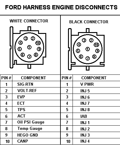
For those parts in your photo, they all have plug names
Mustang Electrical and Vacuum diagrams.
Awesome color wiring diagram, by TMoss, for the 88-91 Mustang 5.0 Injectors, Sensors, and Actuators:
http://www.veryuseful.com/mustang/tech/engine/images/88-91_5.0_EEC_Wiring_Diagram.gif
"http://www.veryuseful.com/mustang/tech/engine/images/88-91_5.0_EEC_Wiring_Diagram.gif"
Now, go back and find the items under the hood again...
Name it and claim it time.
Haystack found what I did, no common 1986 GT Emission/ Vacuum Lines diagram.
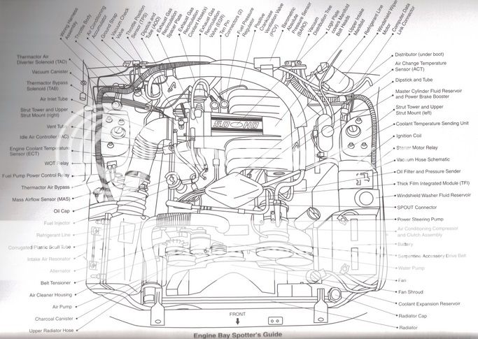

1, 2, 14, 18, 20. 41, 43, 49, 50, 51, 52 and 53 are the critical EGR related parts.
1. Thermactor Air Diverter Solenoid (TAD) - Directs thermactor air from the rear of the cylinder heads to the exhaust H pipe after warm up
2. Thermactor Air Bypass Solenoid (TAB) - Vents thermactor air during periods when it is not needed (primarily cold starts)
3. Vacuum Storage Canister - Stores Vacuum to prevent interruption of services during wide open throttle
4. Throttle Body - Regulates the amount of air entering the engine
5. Air Inlet Hose - Directs air into the throttle body from the mass air meter (Mass air car) or the air box (Speed Density Car)
6. Idle Air Bypass Valve - Regulates the amount of air needed to maintain a smooth idle
7. Engine Coolant Temperature Sensor (ECT) - Reports the coolant temp to the computer
8. Injectors - delivers fuel sequentially to each cylinder
9. Oil Filler Cap
10. WOT Cutout Relay - Kills AC compressor during wide open throttle
11. Fuel Pump relay - The computer activates the fuel pump through this relay
12. Mass Air Flow Sensor - The Electronic device used to measure the amount of air passing through the meter
13. Mass Air Flow Meter - Electrically measures the amount of air entering the engine and reports the information back to the computer
14. Thermactor Bypass Valve - Directs the flow of air supplied by the thermactor (fresh air) pump
15. Alternator
16. Belt Tensioner
17. Air Silencer - Used to muffle incoming air noise (located in the fender)
18. Canister Purge Solenoid - Allows fuel vapors from the carbon canister to enter the intake manifold
19. Air Cleaner Housing - Contains the air filter
20. Thermactor Air Pump - Delivers high volume, low pressure fresh air to the exhaust system
21. Water Pump, Fan, and Fan Clutch
22. Air Conditioner Condenser Connections - Attaches refrigerant lines to air conditioning condenser
23. Center Line Crash Sensor - 90-93 only - triggers air bag in the event of a front end collision
24. Radiator
25. Radiator Cap
26. Coolant Reservoir and Low Coolant Switch (if so equipped)
27. Power Steering Pump
28. Battery
29. Air Conditioning Compressor
30. Spout Check Connector - Must be unplugged when checking initial ignition timing
31. Windshield Washer Reservoir
32. Vacuum Hose Diagram
33. Ignition Coil - under plastic cover
34. Starter Relay - under plastic cover
35. Coolant Temperature Sender - Relates coolant temperature to the gauge in the instrument panel
36. Engine Oil Dipstick
37. Electronic Distributor - Controlled by the computer
38. Front Strut Insulator and Camber Adjustment Plate
39. Upper Intake Plenum
40. Brake Master Cylinder and Booster
41. VIP Test Connectors - computer test ports
42. Windshield Wiper Motor
43. Vacuum Distribution Tee - From left to right the connections are: vacuum source (intake manifold), unused, vacuum reservoir, speed control servo (if equipped with cruise), power brake booster
44. Air Charge Temperature Sensor - Reports the temperature of the air in the intake manifold to the computer
45. Barometric Absolute Pressure Sensor (BAP) - Reports barometric air pressure to the computer
46. Positive Crankcase Ventilation Valve (PCV Valve) - relieves crankcase pressure
47. Fuel Pressure Regulator - Uses intake manifold vacuum to lower the fuel rail pressure during low rpm operation
48. 10-pin connector - Mates the engine wiring harness with the main wiring harness and the EEC computer
49. EGR Vacuum Regulator Solenoid - Controls the vacuum which opens the EGR valve
50. EGR Valve and EGR Position Sensor - Allows exhaust gases to enter the intake passage during various engine speeds. Reports valve position to computer
51. EGR Spacer - Provides a hot gas passage to and from the EGR valve
52. EGR Coolant Hoses - Circulates coolant through the EGR spacer
53. Throttle Position Sensor - Relates the percentage of throttle opening to the computer
54. Transmission Dipstick Tube - Auto trans only
55. Crankcase Ventilation Tube - Allows crankcase fumes to enter the intake system
56. Wiring Harness - Cable system that connects all of the engine's electrical components to the computer in the passenger side kick panel
57. AC Accumulator - Provides a storage area for the refrigerant in the AC system and houses a chemical drier that removes moisture from the refrigerant
58. Vacuum Check Valve - Allows air to flow in only one direction in order to keep vacuum storage canister fully charged
59. Hood Ground Strap
60. AC Low Pressure Switch - Will not allow the air conditioner compressor clutch to energize if refrigerant pressure drops to an unsafe limit
SEE memberlist.php?mode=viewprofile&u=159624
What follows is Non Plug and Play 5.0 1986 HO Mustang V8 related, a Sequential Port EFi and Sequentially injected Speed Density Mustang. It gets downgraded to a non fault coding, bank fire, non sequentially fired, De wired, non EGR, non AIR, non Purge Canistor system without AC.
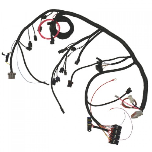
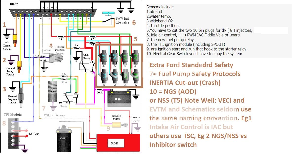
xctasy":1jgddk2e said:An EFI system requires an amazing amount of wire to hook everything up, including fuses, relays, power and ground wires plus sensors and controllers.
But you can get away with as little as this:-
Sensors include
1.air and
2.water temp,
3.wideband O2
4. throttle position.
5.You have to cut the two 10 pin plugs for the wires for the eight ( 8 ) injectors,
6, idle air control, ---->PWM IAC Fiddle Vale or Board
7. the new fuel pump relay
8. the TFI ignition module (including SPOUT)
The only two wires used used from the original harness would be
9. are ignition start and run that hook to the starter relay.
10. Neutral Gear Switch you'll have to copy the system.
See https://www.diyautotune.com/support...d-eec-iv/assembling-the-eec-iv-adapter-board/
What works is mapping out all 37 pins of the MS2 to the 10 outputs.
On my Toyota RAV4, i used John Laughs wiring schematic in paint
"https://www.diyautotune.com/wp-content/uploads/ms_connector.jpg"
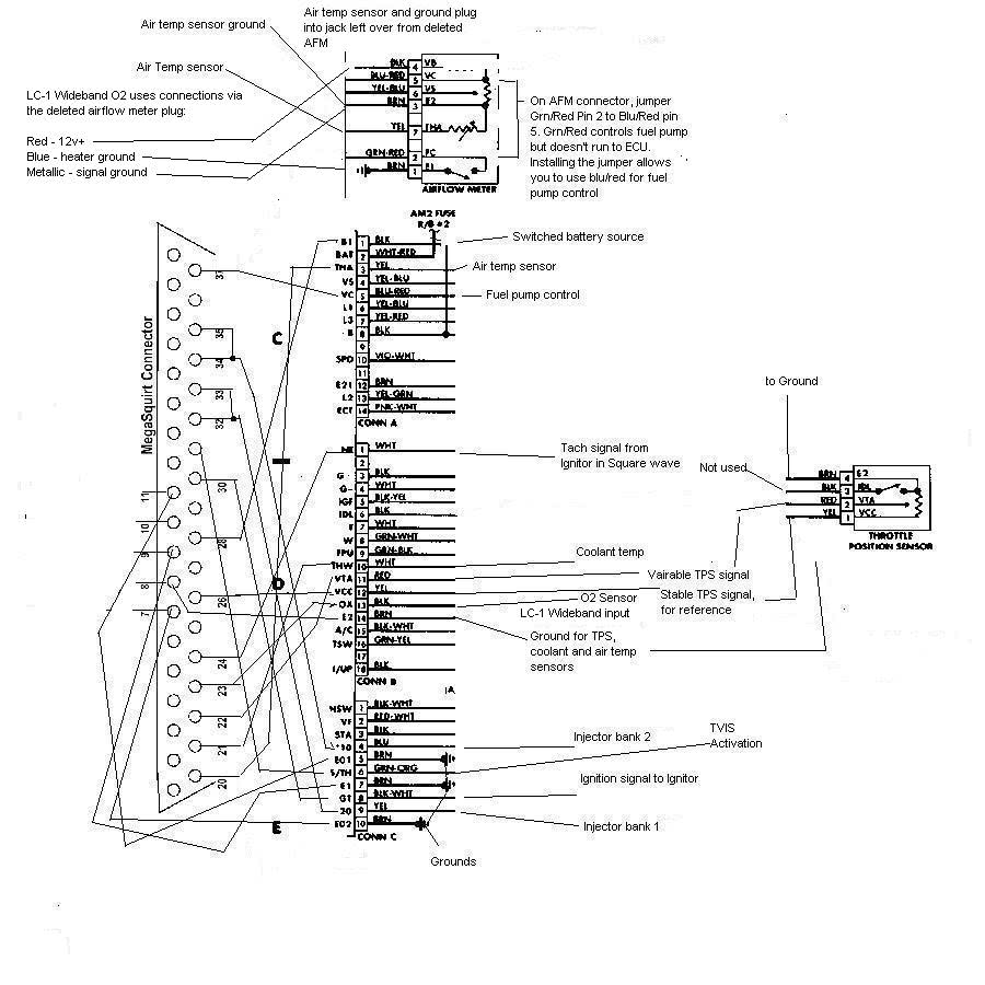
The way to link it all is to take the 37 pin MS2
and match it to the items 1-10 below.
Sensors include
1.air and
2.water temp,
3.wideband O2
4. throttle position.
5.You have to cut the two 10 pin plugs for the wires for the eight ( 8 ) injectors,
6, idle air control, ---->PWM IAC Fiddle Vale or Board
7. the new fuel pump relay
8. the TFI ignition module (including SPOUT)
9. are ignition start and run that hook to the starter relay.
10. Neutral Gear Switch you'll have to copy the system.
All you are doing is making a Wire harness like in item 56 below.
For those parts in your photo, they all have plug names
Mustang Electrical and Vacuum diagrams.
Awesome color wiring diagram, by TMoss, for the 88-91 Mustang 5.0 Injectors, Sensors, and Actuators:
http://www.veryuseful.com/mustang/tech/engine/images/88-91_5.0_EEC_Wiring_Diagram.gif
"http://www.veryuseful.com/mustang/tech/engine/images/88-91_5.0_EEC_Wiring_Diagram.gif"
Now, go back and find the items under the hood again...
Name it and claim it time.
Haystack found what I did, no common 1986 GT Emission/ Vacuum Lines diagram.
Haystack;1794042 said:
Should go to the tab/tad stuff. My guess is that if the vacuum lines are missing, so is the rest.

1, 2, 14, 18, 20. 41, 43, 49, 50, 51, 52 and 53 are the critical EGR related parts.
1. Thermactor Air Diverter Solenoid (TAD) - Directs thermactor air from the rear of the cylinder heads to the exhaust H pipe after warm up
2. Thermactor Air Bypass Solenoid (TAB) - Vents thermactor air during periods when it is not needed (primarily cold starts)
3. Vacuum Storage Canister - Stores Vacuum to prevent interruption of services during wide open throttle
4. Throttle Body - Regulates the amount of air entering the engine
5. Air Inlet Hose - Directs air into the throttle body from the mass air meter (Mass air car) or the air box (Speed Density Car)
6. Idle Air Bypass Valve - Regulates the amount of air needed to maintain a smooth idle
7. Engine Coolant Temperature Sensor (ECT) - Reports the coolant temp to the computer
8. Injectors - delivers fuel sequentially to each cylinder
9. Oil Filler Cap
10. WOT Cutout Relay - Kills AC compressor during wide open throttle
11. Fuel Pump relay - The computer activates the fuel pump through this relay
12. Mass Air Flow Sensor - The Electronic device used to measure the amount of air passing through the meter
13. Mass Air Flow Meter - Electrically measures the amount of air entering the engine and reports the information back to the computer
14. Thermactor Bypass Valve - Directs the flow of air supplied by the thermactor (fresh air) pump
15. Alternator
16. Belt Tensioner
17. Air Silencer - Used to muffle incoming air noise (located in the fender)
18. Canister Purge Solenoid - Allows fuel vapors from the carbon canister to enter the intake manifold
19. Air Cleaner Housing - Contains the air filter
20. Thermactor Air Pump - Delivers high volume, low pressure fresh air to the exhaust system
21. Water Pump, Fan, and Fan Clutch
22. Air Conditioner Condenser Connections - Attaches refrigerant lines to air conditioning condenser
23. Center Line Crash Sensor - 90-93 only - triggers air bag in the event of a front end collision
24. Radiator
25. Radiator Cap
26. Coolant Reservoir and Low Coolant Switch (if so equipped)
27. Power Steering Pump
28. Battery
29. Air Conditioning Compressor
30. Spout Check Connector - Must be unplugged when checking initial ignition timing
31. Windshield Washer Reservoir
32. Vacuum Hose Diagram
33. Ignition Coil - under plastic cover
34. Starter Relay - under plastic cover
35. Coolant Temperature Sender - Relates coolant temperature to the gauge in the instrument panel
36. Engine Oil Dipstick
37. Electronic Distributor - Controlled by the computer
38. Front Strut Insulator and Camber Adjustment Plate
39. Upper Intake Plenum
40. Brake Master Cylinder and Booster
41. VIP Test Connectors - computer test ports
42. Windshield Wiper Motor
43. Vacuum Distribution Tee - From left to right the connections are: vacuum source (intake manifold), unused, vacuum reservoir, speed control servo (if equipped with cruise), power brake booster
44. Air Charge Temperature Sensor - Reports the temperature of the air in the intake manifold to the computer
45. Barometric Absolute Pressure Sensor (BAP) - Reports barometric air pressure to the computer
46. Positive Crankcase Ventilation Valve (PCV Valve) - relieves crankcase pressure
47. Fuel Pressure Regulator - Uses intake manifold vacuum to lower the fuel rail pressure during low rpm operation
48. 10-pin connector - Mates the engine wiring harness with the main wiring harness and the EEC computer
49. EGR Vacuum Regulator Solenoid - Controls the vacuum which opens the EGR valve
50. EGR Valve and EGR Position Sensor - Allows exhaust gases to enter the intake passage during various engine speeds. Reports valve position to computer
51. EGR Spacer - Provides a hot gas passage to and from the EGR valve
52. EGR Coolant Hoses - Circulates coolant through the EGR spacer
53. Throttle Position Sensor - Relates the percentage of throttle opening to the computer
54. Transmission Dipstick Tube - Auto trans only
55. Crankcase Ventilation Tube - Allows crankcase fumes to enter the intake system
56. Wiring Harness - Cable system that connects all of the engine's electrical components to the computer in the passenger side kick panel
57. AC Accumulator - Provides a storage area for the refrigerant in the AC system and houses a chemical drier that removes moisture from the refrigerant
58. Vacuum Check Valve - Allows air to flow in only one direction in order to keep vacuum storage canister fully charged
59. Hood Ground Strap
60. AC Low Pressure Switch - Will not allow the air conditioner compressor clutch to energize if refrigerant pressure drops to an unsafe limit
Here is your tie in wiring.
The EECIV things you have eliminated are:
1. Charcoal Canister Purge---> Now Tank will pressurize
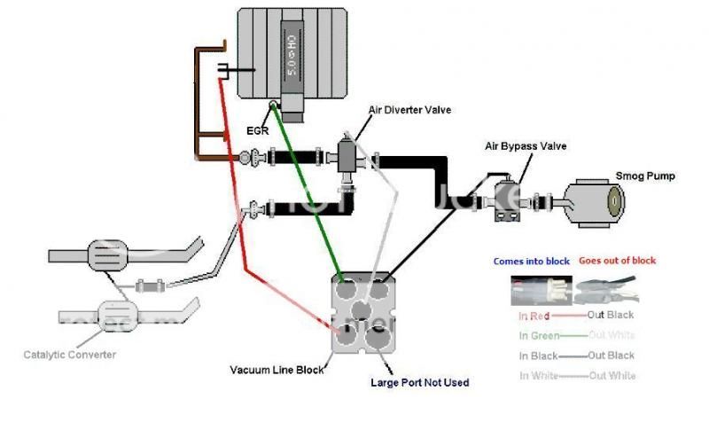
2. Thermactor Diverter and Bypass TAD/TAB (Upstream and downstream AIR control)
3. Fuel Pump FPR control---> Now MS2
4. IAC control----> Now MS2
5. EGR control (Vacuum and Vent Solenoids)---> None
6. What was called Neutral/ Drive Switches
7. An aspect of Crash Inertia Sensor operation ---> None if you don't take steps to re-establish the Fuel Pump FPR control Now by MS2
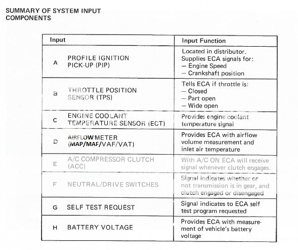
Standard Group EECIV controls were
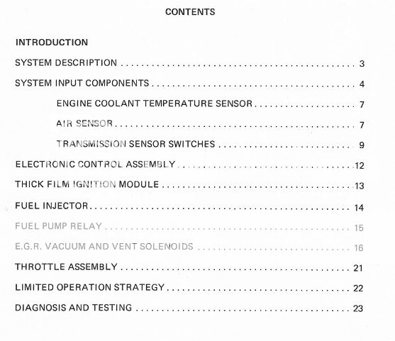
Inputs were:
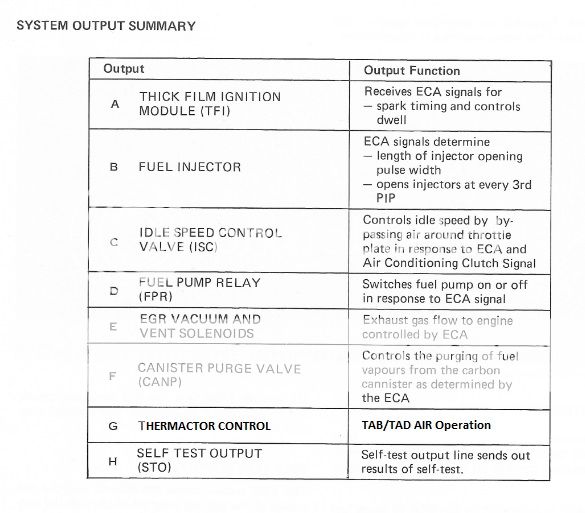
Out puts were
MegaSquirt 2 has an Input/Output/Control system map. so does Fords EECIV.
When anyone goes off the EECIV sheet, they then have to establish
1. another way to ensure the tank doesn't pressurize,
2. the Inertia switch works, and
3. that the Neutral / Drive switches operate.
4. The VSS sensor is just used for Speed control, but is used for other things on some Speed Density Fords.
The EECIV things you have eliminated are:
1. Charcoal Canister Purge---> Now Tank will pressurize
2. Thermactor Diverter and Bypass TAD/TAB (Upstream and downstream AIR control)
3. Fuel Pump FPR control---> Now MS2
4. IAC control----> Now MS2
5. EGR control (Vacuum and Vent Solenoids)---> None
6. What was called Neutral/ Drive Switches
7. An aspect of Crash Inertia Sensor operation ---> None if you don't take steps to re-establish the Fuel Pump FPR control Now by MS2
Standard Group EECIV controls were
Inputs were:
Out puts were
MegaSquirt 2 has an Input/Output/Control system map. so does Fords EECIV.
When anyone goes off the EECIV sheet, they then have to establish
1. another way to ensure the tank doesn't pressurize,
2. the Inertia switch works, and
3. that the Neutral / Drive switches operate.
4. The VSS sensor is just used for Speed control, but is used for other things on some Speed Density Fords.
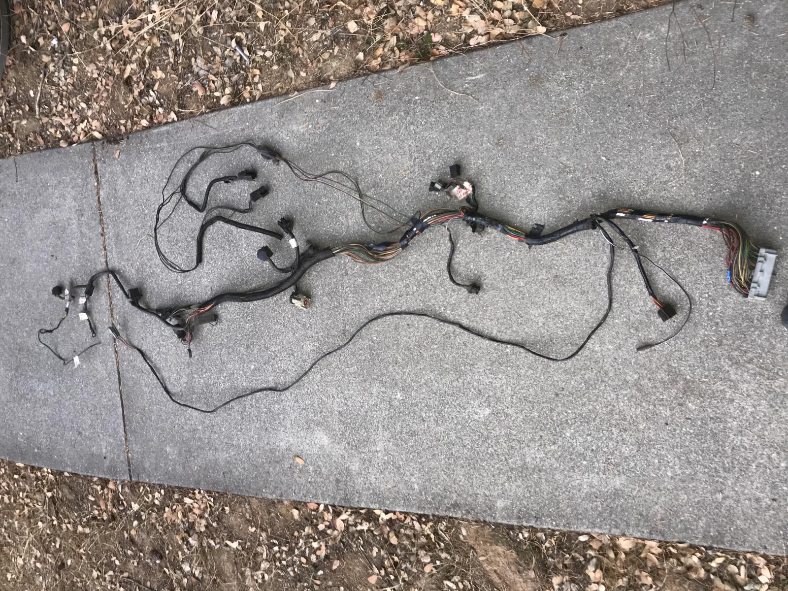
Wiring removal from a previously EECIV equipped truck.
If the fusible links get removed, you really ought to go 3G and power distribution board with Buss bar. Then its feature creep again...like electric fans. All that stuff can steal power and hurt idle and the Fiddle valve is supposed to be able to help restore under load idle speed.
The intake manifold can be swapped 180 degrees, the battery can be relocated, there are many things you can do. Down here, all our 5.0s have the manifold upper reversed and the battery changed positions between 1992 and 2002 on our cars. Just like your Truck Lightenings and the Panther platfrom EFi port injected 5.0s. Great thing is MS2 allows you to do that as well. Hence Thomas and Drew put the Power distribution boards on opposite sides. Which was different between 85 and 86.
http://vb.foureyedpride.com/showthread.php?179999-1985-GT-Build/page3
1>http://vb.foureyedpride.com/showthread.php?142515-Purge-valve
note Nigel... in this case VAM is MAF, and the purge valve goes into the positions here below.
86 and 87 5.0 HO's differ only slightly
Mar 23, 2016 https://www.stangnet.com/mustang-fo...nection-on-a-1987-intake.890038/#post-8960203
Since EECIV is now gone burger, and the wires to Pin 31, and Pin 37/ 57 are to invoke Vacuum Pulse Width Modulation cycling at about 200Hz at 100% duty cycle, then I'd suggest you manually purge with a rocker switch when required.
for Purge
EGR (http://vb.foureyedpride.com/showthread.php?177608-Installing-an-EGR-system)
even the Fox LTD/Marquis/ Lincoln/Panther Trip Minder (http://vb.foureyedpride.com/showthr...C-IV-Pin-34-Data-Output-Link-PWM-Data-produce) ,
there is a project wiring process that can be laced in later on. mrriggs is a member at FEP, FSP and at http://www.gofastforless.com
He does a whole bunch of TFi/EGR/TripMinder stuff for a small fee that others charge 500 dollars a try...
http://www.gofastforless.com/ignition/EEConomizer.gif
2>http://vb.foureyedpride.com/showthread.php?177115-Inertia-switch-and-fuel-pump
read all 9 posts. Walking-Tall's got it all together..
3>http://vb.foureyedpride.com/showthread.php?114031-Can-I-add-a-clutch-safety-switch
read all 18 posts. IMHO, the 306gt solution is a good one. Doesn't have to be linked to the CPU/ECM/MegaSquirt
Do take the time out to sort through this but remember....what to leave in and what to take out can be optional to you....you don't have to do it all. Those browny orange options are for the Ford nice to haves. For your own sanity, you can leave them out until you've got the basics right. It doesn't have to be a 12 out of 10 from the get go. MegaSquirt has always been a Ford benefit match...its simplicity is why it has grown so much.
If the fusible links get removed, you really ought to go 3G and power distribution board with Buss bar. Then its feature creep again...like electric fans. All that stuff can steal power and hurt idle and the Fiddle valve is supposed to be able to help restore under load idle speed.
The intake manifold can be swapped 180 degrees, the battery can be relocated, there are many things you can do. Down here, all our 5.0s have the manifold upper reversed and the battery changed positions between 1992 and 2002 on our cars. Just like your Truck Lightenings and the Panther platfrom EFi port injected 5.0s. Great thing is MS2 allows you to do that as well. Hence Thomas and Drew put the Power distribution boards on opposite sides. Which was different between 85 and 86.
http://vb.foureyedpride.com/showthread.php?179999-1985-GT-Build/page3
nigel":19ni0l63 said:Thank you for the breakdown, this helps bigtime. Im currently in the parts gathering stage; gonna try and find an sn95 relay/fuse mount if i can, or just mount an aftermarket fuse block on some kind of nonconductive panel on the passenger fenderwell, new plugs for the sensors, and one chip for the ms2 thats fried and im gonna have to pay shipping for lol
1. another way to ensure the tank doesn't pressurize,
does the fuel cap being vented not serve this purpose?
2. the Inertia switch works, and
3. that the Neutral / Drive switches operate.
and if they dont? wont it be like an older car that you can just start with the clutch engaged?
1>http://vb.foureyedpride.com/showthread.php?142515-Purge-valve
martin0660":19ni0l63 said:Not 100% clear on the question, but the EFI 2.3 turbo stuff had a simple system. The vent line from the tank went to the charcoal canister, then a flex line (I think what you describe as cheap flex) went to an elbow between the stock air filter housing and the VAM meter. Anything coming off the canister was drawn into the VAM then into the engine. No solenoid, no control at all.
I think this is what you was asking about.
note Nigel... in this case VAM is MAF, and the purge valve goes into the positions here below.
86 and 87 5.0 HO's differ only slightly
The 86 upper intake has unique porting
The 86 PCV long hose that does a 180 degree loop
Mar 23, 2016 https://www.stangnet.com/mustang-fo...nection-on-a-1987-intake.890038/#post-8960203
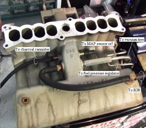
jrichker StangNet's favorite TOOL":19ni0l63 said:Notice the large rubber hose that goes off screen....That connects to the solenoid valve that connect to the charcoal canister that connects to the....

Charcoal canister plumbing - one 3/8" tube from the bottom of the upper manifold to the rubber hose. Rubber hose connects to one side of the canister solenoid valve. Other side of the solenoid valve connects to one side of the canister. The other side of the canister connects to a rubber hose that connects to a line that goes all the way back to the gas tank. There is an electrical connector coming from the passenger side injector harness near #1 injector that plugs into the canister solenoid valve. It's purpose is to vent the gas tank. The solenoid valve opens at cruse to provide some extra fuel. The canister is normally mounted on the passenger side frame rail near the smog pump pulley.

It does not weigh but a pound or so and helps richen up the cruse mixture. It draws no HP & keeps the car from smelling like gasoline in a closed garage. So with all these good things and no bad ones, why not hook it up & use it?
The purge valve solenoid connector is a dangling wire that is near the ECT sensor and oil filler on the passenger side rocker cover. The actual solenoid valve is down next to the carbon canister. There is about 12"-16" of wire that runs parallel to the canister vent hose that comes off the bottom side of the upper intake manifold. That hose connects one port of the solenoid valve; the other port connects to the carbon canister.
The purge valve solenoid should be available at your local auto parts store.
Purge valve solenoid:

The carbon canister is normally mounted on the passenger side frame rail near the smog pump pulley.
Carbon Canister:

Since EECIV is now gone burger, and the wires to Pin 31, and Pin 37/ 57 are to invoke Vacuum Pulse Width Modulation cycling at about 200Hz at 100% duty cycle, then I'd suggest you manually purge with a rocker switch when required.
for Purge
EGR (http://vb.foureyedpride.com/showthread.php?177608-Installing-an-EGR-system)
even the Fox LTD/Marquis/ Lincoln/Panther Trip Minder (http://vb.foureyedpride.com/showthr...C-IV-Pin-34-Data-Output-Link-PWM-Data-produce) ,
there is a project wiring process that can be laced in later on. mrriggs is a member at FEP, FSP and at http://www.gofastforless.com
He does a whole bunch of TFi/EGR/TripMinder stuff for a small fee that others charge 500 dollars a try...
http://www.gofastforless.com/ignition/EEConomizer.gif
mrriggs":19ni0l63 said:After wasting a day farting around with the PIC micro, I decided it wasn't worth the effort. It would require an external clock to match the accuracy of the SX chip which would negate it's advantage of a smaller footprint. Plus, I don't have an in-circuit programmer for the PIC so I'd have to pull the chip out any time I wanted to tweak the calibration.
Here is the schematic for the calibrator using the SX18AC;
"http://www.gofastforless.com/junk/FuelFlowCalibrator.gif"
And the finished circuit board;
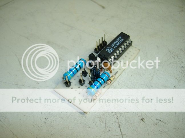
"http://www.gofastforless.com/junk/FuelFlowCalibrator01.jpg"
I neglected to consider the current draw of the in-circuit programmer when picking values for the shunt regulator. I plugged it in and the voltage drops to 3 Volts. Oh well, it works as it should when the programmer isn't plugged in. Don't really want to up-size the shunt regulator to accommodate the programmer since that will just add heat and waste power. Instead, I'll make a dongle for the programmer to power it from a separate source.
2>http://vb.foureyedpride.com/showthread.php?177115-Inertia-switch-and-fuel-pump
read all 9 posts. Walking-Tall's got it all together..
moaction":19ni0l63 said:I've got a 84 Mustang Convertible that was converted from 3.8 fuel injection to 302 carb and I'm trying to figure out the wiring layout of the Inertia switch since I think it has been removed. I can't find the switch in the trunk.
There are two wires that exit through the floor on the passenger side just in front of the back seat. I think they are a black wire and white wire.
Once under the car the wires are cut. One is not connected to anything and the other is connected to the positive side of the coil. For 12v power I assume. There is no power to the intank fuel pump plug that I was hoping to use power from there to run an external Holley pump.
I'm right in thinking the two cut wires are for the inertia switch and why would one of the wires need 12v power?
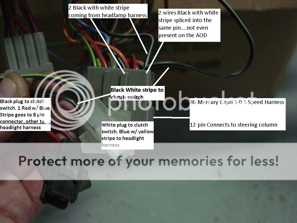
3>http://vb.foureyedpride.com/showthread.php?114031-Can-I-add-a-clutch-safety-switch
read all 18 posts. IMHO, the 306gt solution is a good one. Doesn't have to be linked to the CPU/ECM/MegaSquirt
FoxFleet":19ni0l63 said:I am doing an 86 AOD to 5 Speed conversion, my AOD does not have these 2 connectors for the clutch switch, but I am adding them from an 86 5 speed harness.
I am confused on that same white connector with the Blue/yellow wire, the other wire is a black wire not present on my AOD harness...any idea if I need to add that wire?
Do take the time out to sort through this but remember....what to leave in and what to take out can be optional to you....you don't have to do it all. Those browny orange options are for the Ford nice to haves. For your own sanity, you can leave them out until you've got the basics right. It doesn't have to be a 12 out of 10 from the get go. MegaSquirt has always been a Ford benefit match...its simplicity is why it has grown so much.
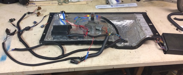
Plenty of MegaSquirts exist in the wild
MechRich's from https://www.therangerstation.com/forums/index.php?threads/ricks-5-0-c6-swap-1985-bii.188737/
MechRich's from https://www.therangerstation.com/forums/index.php?threads/ricks-5-0-c6-swap-1985-bii.188737/
Similar threads
- Replies
- 0
- Views
- 312
- Replies
- 9
- Views
- 223
- Replies
- 15
- Views
- 643
- Replies
- 3
- Views
- 192