EEC-IV basics

Regarding your issue with the fuel pump relay; it could very well be more of a problem in the plug itself. I have seen the wiring insulation deteriorate and also the wire strands breaking causing the resistance to increase. Have you tried replacing the electrical connector to the relay?

S-659​

Electrical Connector​

STD

POP: D​

Per Car: 1​

Thanks for the suggestion. I have been through the fiel system as far as new pumps. And new sending unit. I also removed and re sealed the tank. I noticed that the factory wires at the plug are a bit worn. I was considering just running all new wires for the injection system from the relay.
While swapping to the more common configuration relay at the same time.
 
I have troubling questions.

Did the 351 and 460 ever get CFI, or did they go from VV carbs directly to mpfi?

Does the CFI run its two injection in perfect sync, or are they independently fired?

On the batch fire motors, how many batches are there? 2 or 3 for sixes, 2, 3, or 4 for V8s?

If the answer is 2 for both, than is there any actual difference between between the CFI ECUs and the batch fire ones, other than the fuel/timing tables on the ROMs and the amount of injectors on the output lines?

Will a 5.0 CFI run a 300 six with the appropriate sensors, distributor, and intake, like Clifford with a 2BBL adaptor? If yes, then will the Canadian Essex 3.8's CFI system run a 240 with said setup, seeing as there is less than 1% difference in them, displacement-wise?

Is the Essex 3.9 V6 setup speed density?
 
Last edited:
MechRick,

Thank you for posting all of this information! These older injection systems are simple and reliable but can be difficult to diagnose at times.
 
Head is spinning but I think I got most of it. This really helped lay out what I need to grab when I head back to the junk yard for my MAF conversion.
 
I've been wanting to do a thread on EEC-IV for a while now.
Have to add that this is an awesome info-dump. Thanks so much for taking the time to put it together in a digestible format. Info and data is always useful, but experience is what makes the info applicable and in-context.
Does the CFI run its two injection in perfect sync, or are they independently fired?

On the batch fire motors, how many batches are there? 2 or 3 for sixes, 2, 3, or 4 for V8s?
While the early EEC could be used for CFI/TBI, you "get what you get", and operational or tuning changes are both complex and limited. It has become far more common to use inexpensive aftermarket ECMs to configure setup and operation of both fuel and ignition in the best way for your use. Independent injector firing control, firing injectors at any crank angles you like, and how many times per-cycle you choose and test as best, e.g., 2 injectors, alternating, firing 3 times each per-cycle, for 6 evenly-spaced injections.

Like Starbucks and coffee, MegaSquirt started it all and many others are now filling the space of custom DIY EFI. 2-channel ECMs are under $100 (CFI or 3x2 MPFI and distributor), and 4-channel (paired MPFI injectors on 3 channels and waste spark coil packs) are under $200. They are also designed for user tuning with dashboard and tuning analysis programs (not a manipulation of the proprietary Ford or other system) that tune logically more like carbs, making better operation within grasp for the average hobbyist. Something to think about to make older but robust hardware such as the 2V CFI very useful.
 
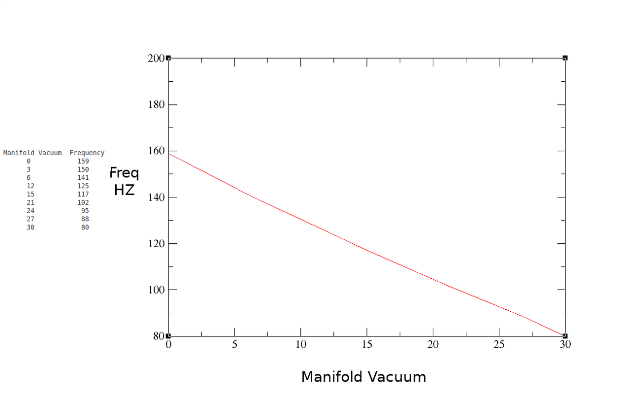
Ford decided to forge an unusual path when it comes to Manifold Atmospheric Pressure (MAP) sensors. Most manufacturers chose a simple 0-5v signal, with decreasing manifold pressure indicating less voltage at the sensor output. Ford used a frequency generator instead.

Ford uses a 5v input, and the sensor is grounded through signal return as other manufacturers. The output however, is a 5v square wave whose frequency varies with manifold pressure.

Typical sensor values will swing between approximately 100 HZ at idle and 151 HZ at wide open throttle. Accurate diagnosis requires a frequency meter. Nowadays they can be bought cheaply, back in the 80's they were prohibitively expensive for the average technician. We resorted to Ford's method for checking sensor output, which is setting a voltmeter to DC volts and looking for around 2.5 volts on the center MAP output pin (5 volts at a 50% duty cycle equals an average of 2.5 volts). This won't tell you the frequency of the signal, but will tell you if the sensor is completely dead.

Many MAP issues were actually vacuum issues. Hydrocarbon vapor can dissolve the potting inside the sensor, which can plug the vacuum hose. Rubber vacuum hoses crack and split, vacuum nipples on intakes plug with carbon.

A spare MAP sensor is something every Ford tech had in his toolbox for diagnosis.
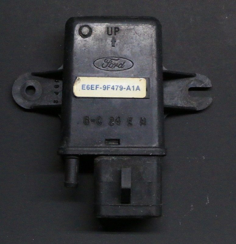


MAP and BARO sensors are identical, BARO sensors will not have a vacuum hose attached to them. Be careful when looking at BARO PID's, as Mass Air vehicles may show the PID, but not have a BARO sensor installed. These vehicles will use WOT airflow data to calculate (infer) BARO PID data.
Looks like these can read up to 15psi of boost at 300mhz. It’s a hard coded limit in the ECM code for like 162mhz that looks it can be changed. Going to attempt a turbo eeciv tune this summer on my truck with this map sensor
 
Standard analog MAP sensors can use a tiny analog-PWM converter, making almost any MAP sensor usable. Inexpensive. Hit me when you get there,
 
Back
Top