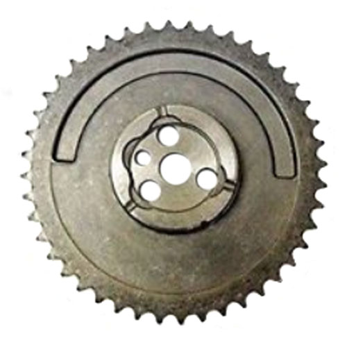
Not to worry, oil holes are there!I am sure that it's the camera angle, but I do not see any oil holes.
You are using an out of date browser. It may not display this or other websites correctly.
You should upgrade or use an alternative browser.
You should upgrade or use an alternative browser.
'76 F250 Turbo Build
- Thread starter jgavac
- Start date
Been a busy weekend, but managed to get the rockers in this morning. With this, I basically reached my goal of having the rotating assembly done by Christmas (technically 1 day after, but I'll take it!)
Gotta get on ordering the remaining parts now. Budget is running a bit tight, so we'll see how quickly I can progress from here.

Gotta get on ordering the remaining parts now. Budget is running a bit tight, so we'll see how quickly I can progress from here.
Got this bad boy delivered yesterday. It's a much thicker casting than I thought it was going to be, but it's not a bad thing because it won't flex. Per Aussiespeed's website I'll need to figure out how I'm going to take an inch off the breather tubes, since they interfere with the wide roller rockers.
On an unrelated note, does anyone know what threads are on the front of the camshaft? I lost my retainer bolt at some point

On an unrelated note, does anyone know what threads are on the front of the camshaft? I lost my retainer bolt at some point
Nice Valve Cover!
The reason you can't find the bolt for the camshaft is because it doesn't use one. LOL
I don't think there is room behind the timing cover even if you wanted to put a bolt and washer on it.
The cam gear is pushed toward the engine block by the crankshaft gear.
The reason you can't find the bolt for the camshaft is because it doesn't use one. LOL
I don't think there is room behind the timing cover even if you wanted to put a bolt and washer on it.
The cam gear is pushed toward the engine block by the crankshaft gear.
The reason you can't find the bolt for the camshaft is because it doesn't use one. LOL
By God, you're right. I could have sworn my Haynes manual called one out, but I just checked the exploded diagram and there's not one there

Felt really wrong to cut into this, but I was able to cut down the breather tubes. In a perfect world I'd have used a mill, but in a pinch a hacksaw and a file worked out pretty well.
I've got it resting on the head and ran the rockers through a couple revolutions and it feels like maintains about 1/16 to 1/8th inch through the full motion.
One thing I hadn't considered was the significantly thicker flange, so I'll need to pick up some longer bolts.

I've got it resting on the head and ran the rockers through a couple revolutions and it feels like maintains about 1/16 to 1/8th inch through the full motion.
One thing I hadn't considered was the significantly thicker flange, so I'll need to pick up some longer bolts.
Last edited:
While talking with the people over on the MS Extra forum, they mentioned actually just using the fuel pump lobe on the cam and a hall effect sensor to work as a basic cam sync signal. Reportedly, when using a 36-1 wheel the MS3X can get by just using a simple cam signal. This was the article I was referenced

 www.diyautotune.com
I'm still going to try using the V6 cam sync sensor I picked up since I already have it and it's long past the return window, but this could be a good backup. Also gets me wondering if it would be possibe to request a sharper, more prominent grind to the pump lobe on a custom camshaft to give a cleaner signal...
Adding a camshaft or crankshaft position sensor
Learn how to add crankshaft & camshaft position sensors for sequential fuel injection using simple tools. A DIY guide for carb-to-EFI conversions.
I'm still going to try using the V6 cam sync sensor I picked up since I already have it and it's long past the return window, but this could be a good backup. Also gets me wondering if it would be possibe to request a sharper, more prominent grind to the pump lobe on a custom camshaft to give a cleaner signal...
The signal won't be any cleaner with a different style lobe, it'll just be shorter or longer in time or degrees of rotation between events, as long as you're using a hall effect sensor and it's proximity is close enough to the lobe to trigger. I believe you'll select if you're using only the rising edge or the falling edge of the signal and where that might be in relation to #1 TDC during the setup. It's been a while since I've looked at the trigger options in TS and they may have changed a bit depending on firmware versions. And as they mention the cam signal doesn't need to be as accurate as the crank signal, since it's just for #1 reference and has a big window of time to indicate it's coming up.While talking with the people over on the MS Extra forum, they mentioned actually just using the fuel pump lobe on the cam and a hall effect sensor to work as a basic cam sync signal. Reportedly, when using a 36-1 wheel the MS3X can get by just using a simple cam signal. This was the article I was referenced
Adding a camshaft or crankshaft position sensor
Learn how to add crankshaft & camshaft position sensors for sequential fuel injection using simple tools. A DIY guide for carb-to-EFI conversions.
I'm still going to try using the V6 cam sync sensor I picked up since I already have it and it's long past the return window, but this could be a good backup. Also gets me wondering if it would be possibe to request a sharper, more prominent grind to the pump lobe on a custom camshaft to give a cleaner signal...
Firepower354
Famous Member
I'm leaning towards milling a groove half way around the cam gear, and picking up the 1x signal there
The signal won't be any cleaner with a different style lobe, it'll just be shorter or longer in time or degrees of rotation between events, as long as you're using a hall effect sensor and it's proximity is close enough to the lobe to trigger.
I guess 'Cleaner' wasn't quite the word I was looking for. What I was trying to say was, given that hall effects work on magnetic fields and the strength of the signal is correlated to the distance the sensor is away from the magnet/lobe, having a steeper ridge would mean fewer degrees of the lobe are within sensing distance, making for more defined peaked waveform than one with a more gradual ramp angle. It's also possible I'm entirely overthinking it, wouldn't be the first time.
I'm pretty sure you are confusing a hall effect sensor with a VR sensor. Hall effect sensor output is either off or on, i.e. a square wave. A VR sensor output is more of a sign wave on which the signal strength or amplitude varies with rpm or sensor distance.I guess 'Cleaner' wasn't quite the word I was looking for. What I was trying to say was, given that hall effects work on magnetic fields and the strength of the signal is correlated to the distance the sensor is away from the magnet/lobe, having a steeper ridge would mean fewer degrees of the lobe are within sensing distance, making for more defined peaked waveform than one with a more gradual ramp angle. It's also possible I'm entirely overthinking it, wouldn't be the first time.
Got it, I was definitely mixing those upI'm pretty sure you are confusing a hall effect sensor with a VR sensor. Hall effect sensor output is either off or on, i.e. a square wave. A VR sensor output is more of a sign wave on which the signal strength or amplitude varies with rpm or sensor distance.

We try to keep it a secret so it will be a surprise.Went to get the oil pump installed today, and it's running into the #4 stud. Is this a known issue that I missed?
Just Kidding!
There is sticky you missed at the beginning of the Big Block section.
All Big Six - ARP Main Studs/Oil pump clearance
I wanted to share the problem and fix of running ARP main studs and the new standard flow melling pump clearance problem. The main studs in the ARP kit were too high for oil pump clearance and the oil pick up tube didn't have threads to grab. I called ARP and got two Bolts sent to me (reference...
There is sticky you missed at the beginning of the Big Block section.
It was even a sticky lol
On a very unrelated note, the HD manifold has a large hole at the back, I'm guessing a heat riser or such? Does anyone know what the threads are on it so I can get something to plug it
I also found while mocking up the intake/exhaust manifolds (I did finally get a lower efi intake last month, not sure I ever mentioned it), looks like the flanges are different thicknesses. OFC I left my calipers at my rental, so tape measure shows the intake is about 0.375" thick while the HD manifold is 0.5" thick.
Given the way these bolt down, the only option I see is having the exhaust milled down to match the thickness of the intake? I'm open to other ideas though


Given the way these bolt down, the only option I see is having the exhaust milled down to match the thickness of the intake? I'm open to other ideas though
Do not mill the exhaust manifold thickness.I also found while mocking up the intake/exhaust manifolds (I did finally get a lower efi intake last month, not sure I ever mentioned it), looks like the flanges are different thicknesses. OFC I left my calipers at my rental, so tape measure shows the intake is about 0.375" thick while the HD manifold is 0.5" thick.
Given the way these bolt down, the only option I see is having the exhaust milled down to match the thickness of the intake? I'm open to other ideas though
Make a very thick stepped washer
Last edited:
Try a 3/4"-14 pipe plug.On a very unrelated note, the HD manifold has a large hole at the back, I'm guessing a heat riser or such? Does anyone know what the threads are on it so I can get something to plug it
What is the ID of the hole?
Similar threads
- Replies
- 4
- Views
- 206
- Replies
- 157
- Views
- 6K
- Replies
- 15
- Views
- 1K
- Replies
- 17
- Views
- 1K
All Small Six
250 Engine Build
- Replies
- 41
- Views
- 2K