'76 F250 Turbo Build

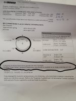
Is it for oiling purposes? Already got rid of the old cam so I had nothing to reference
If the groove lines up with an oil hole then it is for improved oiling.
You are not the first one to question the cam groove.
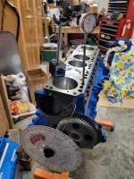
 
This degreeing process has been a bit tedious, but I've got some numbers. First my process (following instructions in the degreeing kit), in case I made any errors;
  1. Installed cam and crank gears with timing points lined up
  2. Used dial indicator to find TDC off the piston, and aligned degree wheel and pointer accordingly.
  3. Using lifter on #1 intake and a pushrod, found high point of intake lobe, set indicator to zero.
  4. Rotate CCW until 0.050 before max lift, 67.5°
  5. Rotate CW until 0.050 after max lift, 157.5°
  6. Theoretical intake CL is (67.5+157.5)/2 = 112.5°.
Per the Crower cam card, intake CL is 110° and should be set as such when using the "lobe center" method of degreeing. Based on this then, the cam is installed 2.5° retarded?

20211107_133553.jpg

20211107_133642.jpg
 
This degreeing process has been a bit tedious, but I've got some numbers. First my process (following instructions in the degreeing kit), in case I made any errors;

Let's start from the beginning.

When you are setting the degree wheel to TDC the connecting rod must be pushing the piston up towards the dial indicator when you take the reading so that the rod bearing clearance does not introduce an error.
Zero the dial indicator with the piston at TDC then turn the crank CCW and pull the piston past .050" BTDC, then turn the crank CW pushing the piston up to .050" BTDC.
Then turn the crank CW past TDC and past .050" ATDC, then CCW pushing the piston up to .050" ATDC.
The degree wheel is centered when both .050" readings are close to 11 degrees before and after TDC.

The cam card is asking you to degree the cam using the .050" duration method rather than the centerline method.
The cam card gives you all four .050" timing points.
Intake opens -5 (5 ATDC) and closes 35 ABDC
Exhaust opens 38 BBDC and closes -18 (18 BTDC)

These timing points occur when the cam is advanced 4 degrees.

Zero the dial indicator at the heal of the cam lobe. The .050" points are when the lifter rises .050".
During this procedure the crankshaft is always turned Clockwise. If you reverse direction the cam gear clearance will introduce error.
It is also good practice to turn the crank a few revolutions after the first set of readings and take at least a second set of readings to check repeatability.

After you have finished getting the 4 points from the degree wheel go back and verify that the degree wheel is still zeroed at TDC before tearing the set-up down.
 
Last edited:
Following those steps;
  1. When you say close to 11°, what range are we talking about? I get 10 on one side and 12 to the other
  2. Verified 4x in a row, IVO 8.5°, IVC 36.5°
 
The degree wheel should be 11° on one side and 11° on the other side to be center about TDC so it is 1 degree off center.
Would that make your reading IVO 7.5° or 9.5° if corrected?
 
Last edited:
The degree wheel should be 11 on one side and 11 on the other side to be center about TDC so it is 1 degree off center.
Would that make your reading IVO 7.5 or 9.5 if corrected?

Checking my notes, I had 12° BTDC, 10° ATDC. Mathematically then, that would put IVO at 7.5 and IVC at 37.5, or 2.5 degrees off the cam card? Unless I'm making the wrong jump to a conclusion.
 
Checking my notes, I had 12° BTDC, 10° ATDC. Mathematically then, that would put IVO at 7.5 and IVC at 37.5, or 2.5 degrees off the cam card? Unless I'm making the wrong jump to a conclusion.
The midway point between 7.5 ATDC and 37.5 ABDC is 111.5 ATDC which is close enough.
That puts the cam 2.5 degrees advanced instead of 4 degrees and seeing that the offset cam keys will change the timing by 4 degrees I would call it good.

If re-centering the degree wheel makes the IVO 9.5 instead that puts the intake lobe center at 113.5 ATDC which only has a .5 degree advance.
That caters a little more to the upper rpm range of the power band and also make the engine less prone to detonation.
That is still a good place to be.

You are good with the intake lobe center between straight up (114 ATDC) and 4 degrees advanced. (110 ATDC).
The 4 degree range just shifts the torque curve slightly.
 
Last edited:
Got the head painted and installed over the long week. I also have the rocker shims, so I'm planning to get those installed and hopefully get the length pushrod I need. Things are coming together!

20211127_125923.jpg
 
So running through the checking process on the #1 intake valve, it looks like 10.30" will be the magic number. This was with 0.060 of shims under the pedestal.

One thought I had when spinning this over, does the hydraulic lifter collapsing throw off the reading? If so, how do I prevent that?

20211127_192648.jpg20211127_193430.jpg20211127_194058.jpg
 
The lifter does collapse.
Take an old lifter apart and put a spacer under the plunger so the top of the plunger is about .060” down from the retaining clip.
The .060” will be the lifter preload.

First check that the retainer clip height is that same for both the old and new lifters.
 
Going with the solid lifter method, I come up with approximately 10.1875. Any longer and the pushrod would start to open the valve when tightening down

20211204_140807.jpg
 
Looks good. How far down is the lifter plunger from the retaining clip on the solid lifter?
 
Looks good. How far down is the lifter plunger from the retaining clip on the solid lifter?

I'll admit when I was putting spacers in the lifter body a couple weekends back, I didn't have a great way to check the plunger distance down since all my feeler gauge sets were too wide to get an accurate reading. But I got it close then took the measurements, since I was going to be away from my shop for a while. I finally got a set of calipers and I'm 0.063 in the hole, from the theoretical centerline of the retaining clip groove.
 
Back
Top