The valves must be across from each other for maximum valve diameter and valve to valve clearance.
Example: If one valve is 2 o'clock (looking at the chamber) the other should be at 8 o'clock.
If you chose to use the Ford 6.2 rocker arms you are pretty much tied to the 6.2 valve placement.
The rocker arms are designed for the 8 degree valve angle.
The distance from the center of the camshaft to the valve tip is determined by the rocker arm length which also determines the spacing between the intake and exhaust valves.
The width of the rocker arms determines the minimum valve offset from the 12 o'clock position.
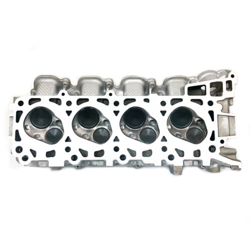
Looking at the chamber with the intake valve sitting up, the intake is at 1 o'clock and the exhaust valve is at 7 o'clock on the passenger side head and 11 o'clock and 5 o'clock on the driver side head.
The head uses two spark plugs per cylinder.