With the Melling RV cam you have lowered the dynamic compression from stock. Regular gas, good to go.@pmuller9 is there a specific timing set and lifters you recommend I use? Also I was just reading some other threads on here and learned about the dynamic compression ratio changing with cam changes. Will this cam be a 93 octane cam? That’s fine if it is I just need to know to run a few tanks of 93 through it before I do the swap. Will I need an adjustable timing set and have to degree the cam or will I be able to just line the marks up and not worry about it?
You are using an out of date browser. It may not display this or other websites correctly.
You should upgrade or use an alternative browser.
You should upgrade or use an alternative browser.
Frank is correct. The Melling cam should allow the use of 87 octane pump gas with a stock EFI engine if it is installed with the correct cam timing.
The Mellling gear sets will work fine.
I like hydraulic flat tappet lifters from Jones Cams
The Mellling gear sets will work fine.
I like hydraulic flat tappet lifters from Jones Cams
I hope everyone who celebrates had a great thanksgiving and got to spend time with family. I’m still working but I might get to go home next weekend. I see from searching the forum that Dynomax Ultra Flo is a good muffler to use to get good performance without a lot of noise. With the plan to go turbo in a year or so would 2.5” be good or should I opt for 3”?Frank is correct. The Melling cam should allow the use of 87 octane pump gas with a stock EFI engine if it is installed with the correct cam timing.
The Mellling gear sets will work fine.
I like hydraulic flat tappet lifters from Jones Cams
So it looks like the fox body mustang kit might have been the better kit to purchase vs the universal kit, but it’s not that big of a difference. Main difference is that the PWM IAC is already wired with the mustang kit. The universal kit comes wired for a 4 wire IAC. I’m considering repinning two of the wires to the correct location for the PWM IAC and removing the other two, but alternatively I might just leave it and order some crimp pins and run the wire for the IAC. That way I can retain the 4 wire style in case I do a different throttle body or something later when I add the turbo.
Also for the coolant temperature sensor, the directions say to install it in a water jacket in either the block or intake manifold, and specifically NOT in a thermostat housing. I assume this is so that the sensor is getting a reading closer to the actual engine temperature and they’re thinking a thermostat housing might not show an accurate temperature until the thermostat opens? But on the EFI 300 the temperature sensor is on the bypass for the heater core and is always getting flow directly from the head. Would it be ok to install a sensor here or should I put it where the sensor for the gauge goes in the block? If I do install in the thermostat housing do you know the thread pitch of that sensor? I might just pull it and go to Lowe’s to see what it threads into.
Also need to know the thread pitch of the IAC sensor so I can order one of those. I’ve tried googling and have seen one person say 3/8npt but would like to be sure. The Holley doesn’t want to use factory sensors unless you can input the sensor data of what resistance they are at specific temperatures.
So for reference for anyone else looking to run a Holley plan on replacing IAT, CTS, MAP, and Oil Pressure.
Install the sensor on the thermostat housing heater bypass tube and it should be fine.Also for the coolant temperature sensor, the directions say to install it in a water jacket in either the block or intake manifold, and specifically NOT in a thermostat housing. I assume this is so that the sensor is getting a reading closer to the actual engine temperature and they’re thinking a thermostat housing might not show an accurate temperature until the thermostat opens? But on the EFI 300 the temperature sensor is on the bypass for the heater core and is always getting flow directly from the head. Would it be ok to install a sensor here or should I put it where the sensor for the gauge goes in the block? If I do install in the thermostat housing do you know the thread pitch of that sensor? I might just pull it and go to Lowe’s to see what it threads into.
Ok cool that’s what I thought. I couldn’t think of a reason it would make a difference.Install the sensor on the thermostat housing heater bypass tube and it should be fine.
Happy new year guys! Got the intake pulled off today, going to make an attempt at the exhaust manifolds tomorrow. Surprised no bolts have broken so far, if it wasn’t for Kroil I’m not sure I would be so lucky. But the studs holding the pipe to the collector are so rusted there’s no visible threads anymore.
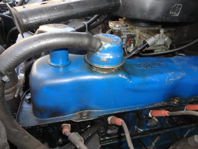
The amount of oil in the intake ports (pic below), is that just from the PCV? And what’s the point of the valve cover having two breathers? There’s the one going from the PCV at the back directly to the intake manifold, and another going from just a regular breather at the front to the air box. Can I delete the PCV and just run the one to the air box? Would I be better off installing a splitter on the one to the air box and plumbing them both in there so the ports don’t get so oily? Run one or both to a catch can?
Also looking like no chance I’m getting the air tubes out of the head, they’re completely rusted together. I’m assuming the solution is to just cut them and crimp them shut? I can also probably clean them up and run a quick bead with the tig after I crimp them to ensure they’re sealed.
Also the Fuel Injector Clinic injectors I bought look like they’ll fit perfectly. I emailed their customer support and asked if I can just buy the ford truck style injectors in a pack of 6 instead of 8, and he said I can use the custom build option to have injectors built however I need or he could give me the part number to a v6 car that uses the same size injectors. I ended up order Volkswagen injectors part number IS166-0445H. Looks like someone previously did the injector upgrade too, the old are the 4 hole injectors instead of the single hole.
There's probably no less than a cup of oil in the upper intake, tip it up in a bucket so it can drain.
There is a downside to port EFI that is overlooked, but has significant long-term impact on engine performance. That is the fact that only dry air is flowing through the intake system. Over time some of the oily vapor of blow by condenses and accumulates in the intake, since there's no fuel to wash it down. But it gets much worse: EGR is pumping exhaust carbon-soot into the intake too. When it combines with the moist oil vapor from the crankcase it makes a thick sludgy goo that coats the runners and plenum. Over time this process can cause flow restriction in the runners and liquid oil accumulation in the plenum, in old engines. Neither of these issues exist on a carburetor intake, the constant flow of fuel washes everything thru the system and into the cylinders.
All answers to your PCV questions are NO.
PCV has to have one side that accesses atmospheric pressure. The valve draws in blow by powered by intake manifold vacuum, working properly it draws slightly more volume than the blow by. The vacuum produced inside the engine draws filtered air into the engine from the side attached to the air filter, in the EFI it's that long hose to the airbox. During heavy throttle blow by is increased and vacuum is diminished. At low vacuum the PCV valve can not keep up with the blow by produced, and the positive pressure in the engine pushes the oily vapors out of the front tube into the air box where they travel thru the piping and back into the intake with the incoming air. Unless you do away with the recirculating system and run a "draft tube", both sides of the system must remain.
Contrary to popular opinion, venting the vapors without the recirculating system has no detrimental effect on the engine, provided the tube is of sufficient size to free-flow without creating backpressure in the crankcase. PCV was created as an emissions standard, it's not necessary for correct engine function. Every engine before the 60's and all diesels until very recently vented the vapor down a tube to the bottom of the engine where they were expelled into the open air. Not suggesting this, just FYI.
If you remove the PCV valve and let all the vapor backflow into the airbox, you will have a filter and airbox full of oil in short order. As already explained above, you can't block off the front tube either if the PCV valve is retained. To reduce under hood clutter, I run the front hose down to the bottom of the engine, with the PCV valve in back. If you do this, you'll need a filter element in the front hose since sometimes air is climbing the hose and entering the valve cover.
Attachments
Ok I get it now. I always thought that all the PCV did was reroute hot oily blow by gases into the intake instead of venting to atmosphere. I didn’t know it also needed the intake tube, I thought they were both venting blow by just to different places. That explains what happened when I replaced the front one. It broke and none of the part stores had a replacement so I just got a universal breather that had a check valve in it. But when I started the truck it would start humming loudly after about ten seconds. I thought it was that the spring valve was too tight and causing the noise when air was opening it, but instead the noise was because it was pulling vacuum and sucking the valve tighter. I ended up just cutting the valve out so it could flow freely like the original.There's probably no less than a cup of oil in the upper intake, tip it up in a bucket so it can drain.
There is a downside to port EFI that is overlooked, but has significant long-term impact on engine performance. That is the fact that only dry air is flowing through the intake system. Over time some of the oily vapor of blow by condenses and accumulates in the intake, since there's no fuel to wash it down. But it gets much worse: EGR is pumping exhaust carbon-soot into the intake too. When it combines with the moist oil vapor from the crankcase it makes a thick sludgy goo that coats the runners and plenum. Over time this process can cause flow restriction in the runners and liquid oil accumulation in the plenum, in old engines. Neither of these issues exist on a carburetor intake, the constant flow of fuel washes everything thru the system and into the cylinders.
All answers to your PCV questions are NO.
PCV has to have one side that accesses atmospheric pressure. The valve draws in blow by powered by intake manifold vacuum, working properly it draws slightly more volume than the blow by. The vacuum produced inside the engine draws filtered air into the engine from the side attached to the air filter, in the EFI it's that long hose to the airbox. During heavy throttle blow by is increased and vacuum is diminished. At low vacuum the PCV valve can not keep up with the blow by produced, and the positive pressure in the engine pushes the oily vapors out of the front tube into the air box where they travel thru the piping and back into the intake with the incoming air. Unless you do away with the recirculating system and run a "draft tube", both sides of the system must remain.
Contrary to popular opinion, venting the vapors without the recirculating system has no detrimental effect on the engine, provided the tube is of sufficient size to free-flow without creating backpressure in the crankcase. PCV was created as an emissions standard, it's not necessary for correct engine function. Every engine before the 60's and all diesels until very recently vented the vapor down a tube to the bottom of the engine where they were expelled into the open air. Not suggesting this, just FYI.
If you remove the PCV valve and let all the vapor backflow into the airbox, you will have a filter and airbox full of oil in short order. As already explained above, you can't block off the front tube either if the PCV valve is retained. To reduce under hood clutter, I run the front hose down to the bottom of the engine, with the PCV valve in back. If you do this, you'll need a filter element in the front hose since sometimes air is climbing the hose and entering the valve cover.
Since vacuum is required for the system to work properly, and I’m planning to turbo in the future anyway, should I just hookup a catch can? Replace the PCV with a regular breather (probably like the one I cut the check valve out of) and route that to a catch can? I assume that’s how you hookup a catch can, I just know all the race car dudes use catch cans when they have forced induction. To prevent the hot dirty air from filling up my intake. I’m already deleting the EGR and purchased a block off plate.
Separately do you know what size the fitting for the air tube for the EGR coming from the manifold is? I don’t have a wrench big enough to remove it and need to buy one. I assume 1 1/8” I have sockets that big just not a wrench.
I'm not sure of the size for the EGR pipe. I removed my EFI intake EGR valve and cut a simple blockoff plate for the top. Used a pipe plug in the exhaust side. Too long ago to remember size.Ok I get it now. I always thought that all the PCV did was reroute hot oily blow by gases into the intake instead of venting to atmosphere. I didn’t know it also needed the intake tube, I thought they were both venting blow by just to different places. That explains what happened when I replaced the front one. It broke and none of the part stores had a replacement so I just got a universal breather that had a check valve in it. But when I started the truck it would start humming loudly after about ten seconds. I thought it was that the spring valve was too tight and causing the noise when air was opening it, but instead the noise was because it was pulling vacuum and sucking the valve tighter. I ended up just cutting the valve out so it could flow freely like the original.
Since vacuum is required for the system to work properly, and I’m planning to turbo in the future anyway, should I just hookup a catch can? Replace the PCV with a regular breather (probably like the one I cut the check valve out of) and route that to a catch can? I assume that’s how you hookup a catch can, I just know all the race car dudes use catch cans when they have forced induction. To prevent the hot dirty air from filling up my intake. I’m already deleting the EGR and purchased a block off plate.
Separately do you know what size the fitting for the air tube for the EGR coming from the manifold is? I don’t have a wrench big enough to remove it and need to buy one. I assume 1 1/8” I have sockets that big just not a wrench.
If you want to eliminate the PCV valve, the simplest solution for your crankcase is to run a tube straight to the bottom of the engine. I've never used a catch can. It's not necessary IMO unless you want to still draw the blow by into the intake. PCV systems are not possible without intake vacuum, any boosted engine can not use it. The hose (3/4" heater hose) in the pic above that exits the front of the engine is all that's necessary. I could remove the PCV valve from the back, block that and then all the vapor will expel out the front. Or remove your PCV valve from the back, get a 90* pipe elbow to fit into the valve cover grommet, attach the 3/4" hose and feed it to the bottom. Without the PCV valve, no filter is necessary, the flow only exhales from the engine side.
The main reason I have the hose like that, and not routed into the air filter like factory is, this engine is at about 98% worn out. There is a relatively high volume of blow by. Anytime the engine is under moderate/heavy load the PCV can't keep up, a lot of vapor is exiting from the front, which would leave oily residue in the filter housing and ruin the paper filter. Look back at the pic again- you'll see oil residue around the breather cap and at the base of the head- that's a tired 300, but still getting the daily chores done.
Got the cam out today, truck will probably start going back together Monday. I would start tomorrow but I need to take the cams to a shop to get the timing gear pressed. I took the distributor apart to modify into a cam sync. @pmuller9 how do I wire this for cam sync? Inside I see 2 green, one red, and one black wire. But coming out of the distributor there is 4 black wires, 2 red, and one green. I assume the blacks are all ground.
bangstk
New member
how do I wire this for cam sync? Inside I see 2 green, one red, and one black wire. But coming out of the distributor there is 4 black wires, 2 red, and one green. I assume the blacks are all ground.
You don't need to mess with any wires on the inside. The output is just a 12V square wave whether it's the original setup or cut down to 1 vane.
Red gets ignition +12V
Black gets signal ground
Green would be the square wave signal positive going to the Terminator.
If you look at the pic here that's pins 1, 7, and 8 respectively on the distributor's connector.
I even suspect you don't need to cut any vanes. One of the vanes is a different size to represent cam reference, so the signal technically already contains a cam signal. The question is whether Terminator X is able to recognize that as a cam signal or not. Since the official Holley Hyperspark distributors have the same sensor and "one vane is smaller" setup as the stock Ford TFI distributors, the rational assumption is it should interpret the unmodified Ford distributor vanes as cam sync if you tell the Terminator software that the cam/crank sensor is a Hyperspark. But, I don't know for certain that it does interpret the Ford/Hyperspark smaller vane as a cam signal. If Holley's TermX can't interpret their own distributor's cam signal then that's just lazy of them...
If it can't interpret Hyperspark/TFI's small vane as cam sync (ugh - that would be silly of holley) then in the worst case you can cut the vanes and then tell the TermX software that the cam sensor is a single pulse signal. (falling edge, I think). Still no wiring change in either case.
Last edited:
Thanks for the reply. After taking the distributor apart I noticed that it did have the one vane smaller for sequential operation but wasn’t sure if the Holley would recognize it properly on a 6 cylinder application vs an 8 cylinder. I was worried when the Terminator “saw” the smaller window after only 6 cylinders instead of 8 cylinders it would mess something up or “confuse” the computer. I was thinking of using the “Ford TFI V8 Sequential” option and not the Holley hyper spark though. I ended up using this other diagram from a 351 truck to determine which pins to use and also ended up with pins 1, 7, and 8. 1 being 12v in, 7 being sensor ground, and 8 being PIP or cam signal out. I also cut it down to one vane and used single pulse or “1x” cam signal.You don't need to mess with any wires on the inside. The output is just a 12V square wave whether it's the original setup or cut down to 1 vane.
Red gets ignition +12V
Black gets signal ground
Green would be the square wave signal positive going to the Terminator.
If you look at the pic here that's pins 1, 7, and 8 respectively on the distributor's connector.
I even suspect you don't need to cut any vanes. One of the vanes is a different size to represent cam reference, so the signal technically already contains a cam signal. The question is whether Terminator X is able to recognize that as a cam signal or not. Since the official Holley Hyperspark distributors have the same sensor and "one vane is smaller" setup as the stock Ford TFI distributors, the rational assumption is it should interpret the unmodified Ford distributor vanes as cam sync if you tell the Terminator software that the cam/crank sensor is a Hyperspark. But, I don't know for certain that it does interpret the Ford/Hyperspark smaller vane as a cam signal. If Holley's TermX can't interpret their own distributor's cam signal then that's just lazy of them...
If it can't interpret Hyperspark/TFI's small vane as cam sync (ugh - that would be silly of holley) then in the worst case you can cut the vanes and then tell the TermX software that the cam sensor is a single pulse signal. (falling edge, I think). Still no wiring change in either case.

The truck has been running for a few months now and I can report with the Melling RV cam, sequential injection, and LS coil pack “coil near plug” ignition I am experiencing a significant increase in power and fuel economy. My truck has 1500-2000lbs in the bed at all times and while stock I averaged 10-12 mpg on the interstate, and always had the throttle estimated over 50-60% to maintain highway speed. Since the swap I’ve recorded 13-16mpg highway. The truck seems to get 13 at 60-75mph but 15-16 at 85mph. My best guess is this is a result of my homemade tune being more efficient at higher rpm and less efficient a little lower. I can also see actual throttle opening and I’m maintaining highway speeds at 25%(60mph)-45%(85mph) throttle. I actually accidentally discovered the better fuel economy by accidentally going too fast because I was holding the throttle open more than necessary out of habit. I’m hoping when I get time off this summer I can get a professional tune and maybe see that 16mpg at the lower speeds too, I’m thinking the engine wants more ignition timing sooner.
I’m planning to make a complete wire diagram for how I wired the truck this summer when I have off time. But less than a week after getting the truck running I had to drive halfway across the country from South Carolina to Coffeyville Kansas for work. Talk about a stressful test drive! But since then I have driven from Kansas to Iowa, back home to South Carolina, and now I’m in Minnesota. No major issues yet. I had an issue of the battery not charging at idle in Kansas and had to idle the truck at 900rpm to keep it charged. I’ve since decided that this was mostly a temperature issue since my battery easily gains voltage at 750rpm now that’s it’s warm, unless the headlights are on. I still drop voltage with headlights on, I’ll probably add the 130a alternator this summer too to help with that.
I think that’s all the updates for now. Any other questions or advice post them and I’ll try to reply. I try to get on a few times a week but it’s hard when you’re working 60-84 hours a week.
Did you save one of the thicker tabs or use the skinny one on the trigger wheel in your distributor?Thanks for the reply. After taking the distributor apart I noticed that it did have the one vane smaller for sequential operation but wasn’t sure if the Holley would recognize it properly on a 6 cylinder application vs an 8 cylinder. I was worried when the Terminator “saw” the smaller window after only 6 cylinders instead of 8 cylinders it would mess something up or “confuse” the computer. I was thinking of using the “Ford TFI V8 Sequential” option and not the Holley hyper spark though. I ended up using this other diagram from a 351 truck to determine which pins to use and also ended up with pins 1, 7, and 8. 1 being 12v in, 7 being sensor ground, and 8 being PIP or cam signal out. I also cut it down to one vane and used single pulse or “1x” cam signal.
View attachment 25391
The truck has been running for a few months now and I can report with the Melling RV cam, sequential injection, and LS coil pack “coil near plug” ignition I am experiencing a significant increase in power and fuel economy. My truck has 1500-2000lbs in the bed at all times and while stock I averaged 10-12 mpg on the interstate, and always had the throttle estimated over 50-60% to maintain highway speed. Since the swap I’ve recorded 13-16mpg highway. The truck seems to get 13 at 60-75mph but 15-16 at 85mph. My best guess is this is a result of my homemade tune being more efficient at higher rpm and less efficient a little lower. I can also see actual throttle opening and I’m maintaining highway speeds at 25%(60mph)-45%(85mph) throttle. I actually accidentally discovered the better fuel economy by accidentally going too fast because I was holding the throttle open more than necessary out of habit. I’m hoping when I get time off this summer I can get a professional tune and maybe see that 16mpg at the lower speeds too, I’m thinking the engine wants more ignition timing sooner.
I’m planning to make a complete wire diagram for how I wired the truck this summer when I have off time. But less than a week after getting the truck running I had to drive halfway across the country from South Carolina to Coffeyville Kansas for work. Talk about a stressful test drive! But since then I have driven from Kansas to Iowa, back home to South Carolina, and now I’m in Minnesota. No major issues yet. I had an issue of the battery not charging at idle in Kansas and had to idle the truck at 900rpm to keep it charged. I’ve since decided that this was mostly a temperature issue since my battery easily gains voltage at 750rpm now that’s it’s warm, unless the headlights are on. I still drop voltage with headlights on, I’ll probably add the 130a alternator this summer too to help with that.
I think that’s all the updates for now. Any other questions or advice post them and I’ll try to reply. I try to get on a few times a week but it’s hard when you’re working 60-84 hours a week.
Thanks
Doesn’t matter. I think I used one of the thicker ones though. If you set it to digital rising it’ll trigger when the tab enters the gap. If you set it to digital falling it’ll trigger when the tab exits the gap. Other than that there’s no difference.Did you save one of the thicker tabs or use the skinny one on the trigger wheel in your distributor?
Thanks
Doesn’t matter. I think I used one of the thicker ones though. If you set it to digital rising it’ll trigger when the tab enters the gap. If you set it to digital falling it’ll trigger when the tab exits the gap. Other than that there’s no difference.
Hey man, I am local to SC and interested in what you did to your truck. I am nowhere near as experienced as some "gear heads," but there are a few issues and experiments I want to do to my truck. I have one with dual tanks and some fuel-related issues I want to take care of. I would love to swap over the ECUs, both for modernization and the ability to tune. I have a few really weird issues while running, and the old ECU probably wouldn't give me anywhere near enough information to actually work off of. I use it for sometimes heavy hauling and some extra power would be a massive upgrade.
How did you deal with the distributor to coil swap? Did have to mod it heavily? Sorry if I missed this in the original post.
Also, I have an automatic. Can a Holly ECU such as yours even drive that? How would that be managed?
Thanks. Sorry if the questions seem dumb. Am a newbie.
Idk a lot about automatics but I know it depends on what year your truck is and which auto it has. The older slush boxes were all analog and didn’t need any input from the engine to operate. Sometime in the 90s they switched to a computer controlled transmission and you would need to get a Terminator X Max or Dominator to run the trans. Or a separate transmission controller. For coil on plug all you do is wire the Holley for that type of ignition. My distributor is still there, but it’s just used as a cam sync now to run sequential injection. I also had to get a custom made 58 tooth crank trigger wheel and use a 96 crank pulley to mount it, then make a mount for the crank position sensor. You should be able to run it using the stock distributor and run it batch fire instead of sequential if you wanted though.Hey man, I am local to SC and interested in what you did to your truck. I am nowhere near as experienced as some "gear heads," but there are a few issues and experiments I want to do to my truck. I have one with dual tanks and some fuel-related issues I want to take care of. I would love to swap over the ECUs, both for modernization and the ability to tune. I have a few really weird issues while running, and the old ECU probably wouldn't give me anywhere near enough information to actually work off of. I use it for sometimes heavy hauling and some extra power would be a massive upgrade.
How did you deal with the distributor to coil swap? Did have to mod it heavily? Sorry if I missed this in the original post.
Also, I have an automatic. Can a Holly ECU such as yours even drive that? How would that be managed?
Thanks. Sorry if the questions seem dumb. Am a newbie.
Starting by 1990 -maybe earlier, that IDK- the trans will not shift correctly if the factory ignition system is removed. It will shift but in "limp mode", will be in OD by 35mph. A stand alone controller will be needed, such as this example.Also, I have an automatic. Can a Holly ECU such as yours even drive that?

Quick 4 Stand-Alone Transmission Control
The Quick 4 controller makes your 4L60E, 4L80E, 4R70W, E4OD, or 4R100 transmission work in a wide variety of vehicles, including ones not originally equipped with electronic control. It also allows customization of the transmission's behavior with user-friendly software.
 www.usshift.com
Similar threads
- Replies
- 3
- Views
- 275
- Locked
- Replies
- 0
- Views
- 13K
- Replies
- 8
- Views
- 13K
- Replies
- 11
- Views
- 23K