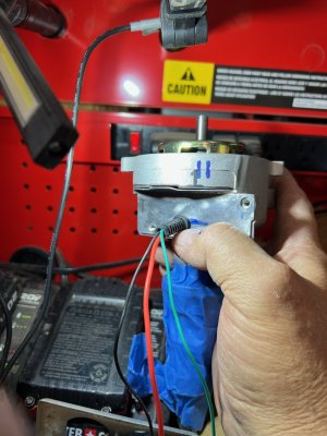
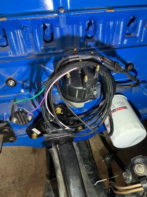
I know I am replying to an old thread, but it is one I have been leaning on for my efforts at converting a Ford TFI distributor to allow it to work with a Sniper EFI to control a Hyperspark ignition. Short Post with my thoughts on closking things to properly work.
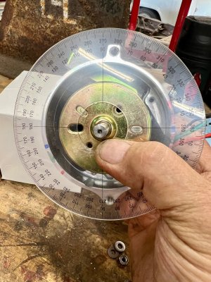
With the shutter wheel's skinny tooth leading edge right at the center of the Hall effect sensor, and the rotor wiper pointed dead-center exactly at the #1 cap post, I am able to measure that the position of the Hall effect sensor at +160 degrees, (clockwise) away from the #1 cap post. Everything I read and see tells me that this is where #1 would get spark if timing were set with zero advance; firing right at TDC.
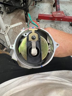
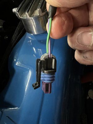
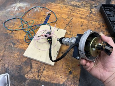
You can see in the pics where I have begun labelling with a Sharpie marker showing the range of acceptable spark firing based on rotor angle, as well as the stock position of the Hall effect sensor for this Ford distributor. The stock position of the Hall effect sensor is the blue mark not quite opposite the rotor wiper.
To clock the Hall effect sensor to match the Holley reference angle of 57.5 degrees, we can sort that the sensor needs to be rotated counter clockwise not quite 30 degrees, but almost 29 degrees; 1=half of 57.5 degrees, since the distributor is rotating half speed. I marked this new location in red.
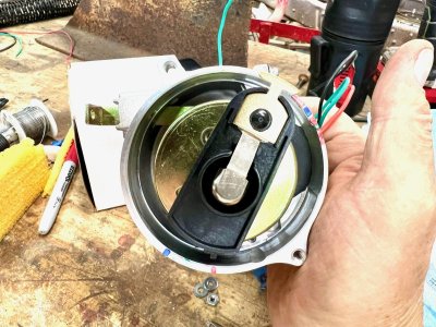
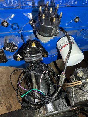
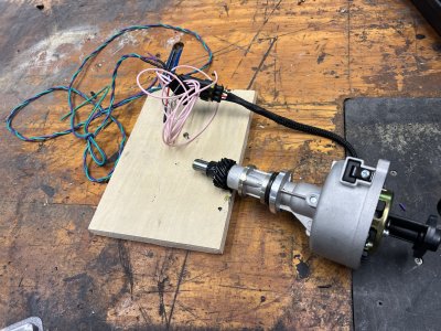
Now the thing in my mind that makes this interesting is that the metal rod that locks the sensor base in place can be slid in and out within the range that seems required to rotate the sensor base to the new correct location. At the 30-ish-degree rotation required to set the distributor to the Holley reference angle, the bar starts to twist off at a bit of an angle, but MAYBE this can be accomodated by fabricating a new bar with an arc shape, or even just an angled external stop. I think I may try to fabricate someting, so stay tuned. I als considered that some precision adjustment could be accomplished by creating a screw stop that captured the bar end, but could be adjusted in and out to fine-tine things after assembly. 'Havent thought this fully through yet, so maybe this is a little too Rube Goldberg, and maybe just a new keeper bar can be fabricated that reclocks things. Note the extended position of the bar in one the last attached pic.
Finally, my thinking is that with all the geometry hopefully figured out, all a guy would need to to is stab the distributor and rotate the base at TDC in such a manner that the rotor wiper lines up it's TRAILING EDGE at about 5-degrees off the #1 cap post so it corresponds with whatever base or idle timing you plan on using. OR, put another way, rotate the motor to 10* BTDC and then stab the distributor so that the trailing edge of the rotor is just "engaged" with the cap post.
All that being said, am I close, did I nail it, or do the experts here have errors in my logic that need discussed? Let me know, and thanks for reading!
This is my first post, even though a long time lurker. Something tells me I need some experience and posts here to be able to share my pictures....