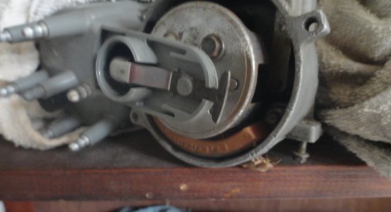
Yes, you could, but is unnecessary — unless you're just curious (which is cool).

Not only is calculating and static visual alignment simpler, but you can look at all the parts and how they relate, to see other options of how to achieve rotor phasing. We're not trying to split hairs here, just have a reasonable alignment at extremes in order to avoid problems. MSD example:
Unfortunately, while you can see if it's reasonable or not, it tells you noting about how to correct it if it's not right.

Also consider the options change depending on the system (EEC, MS, Holley, etc). Most aftermarket DIY systems can use any trigger point and any rotor position to set rotor phase, while others like factory EEC expect a specific position, timing, etc, and are set for that expectation. While total timing for an EFI 300 (and other Ford engines of the early EFI era) could be 28-32°, part-throttle will add another 8-14° to that figure. That's why we can't use the table linked earlier for our final estimates, as it is
incomplete.
A very similar situation is found with the Ford 302/5.0 using E7 heads, which like 30° max at 100% throttle, but pushes timing at part-throttle to 41° total. This means the rotor position is now 10° (base/cranking) to 41° for calculations (31° change). Twist the distributor timing 3° for a bit better
factory performance and it's now 13-44°. The EFI 300 is likely
very similar with factory phasing set appropriately.
Most DIY systems don't care and have no restrictions.
If tuning to other spec than factory, the advance range will also likely change, which affects the rotor range extremes and center position. Again, avoid splitting hairs. Just verify it's reasonably close. Rather than complicating the issue, I'm hoping to let others see that it's actually easier depending on what system you're using, and sticking to the basics of movement and timing relationships for a quick and easy solution using pencil and paper.
, but you can calculate the crank angle where the rotor should be exactly aligned at the cap terminal. This ensures the rotor is as close to centered on the terminal at any advance, reducing spark gap and potential cross-fire. I created this 'formula' to find optimal alignment angle, using base timing and max advance. It makes the job clear and quick. An excerpt from an article I wrote a few years ago:


