RoadWarriorDyno System for XEC engines

xctasy

5K+
VIP
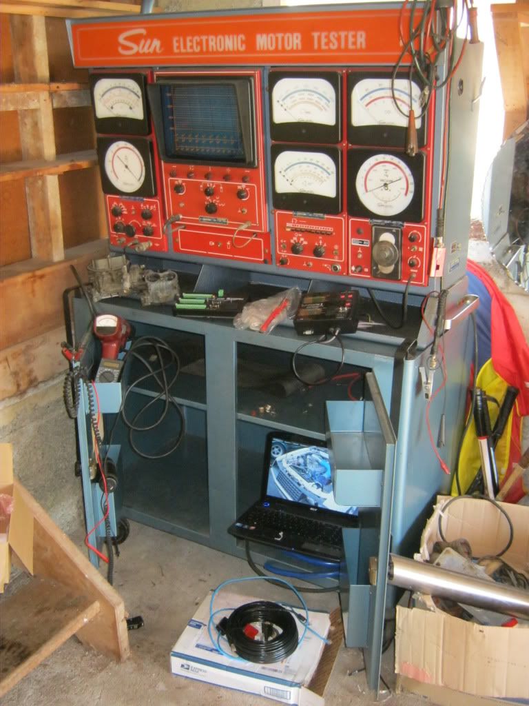
Road Warrior Dyno System details. As it might evoke post apocalyptic state of decay, it is a road workers dynamometer, but with a much greater level or real world repeatablility. Its primary advantage is that it suits a build own operate transfer environment where test equipement is always a whole pacakage of gearbox, engine, carb, exhast, diff ratio and vehicle with a set frontal area and size.

I'm currently putting the finishing touches on the Road Warrior Dyno System. It's basically :-


1. an advanced cruise control defined road load device which allows my engine combinations to be baselined against a set load, a little like the Federal Motor Vehicle emissions test cycle.

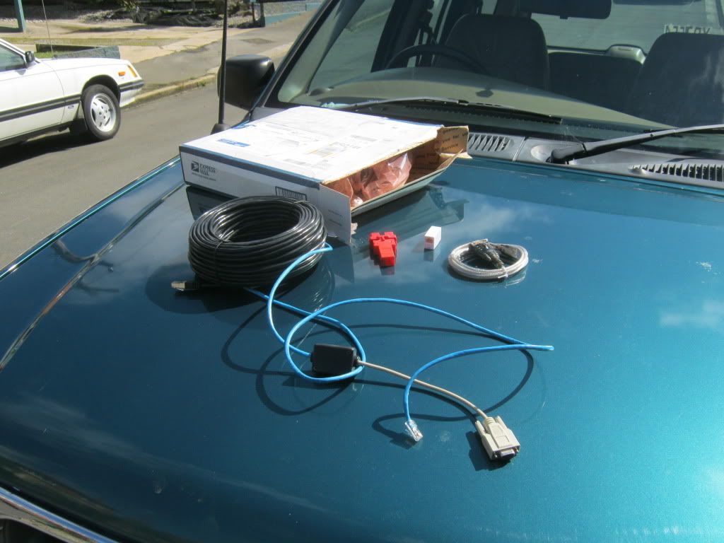
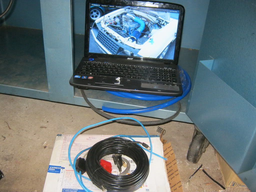
2. It's a spin off from my road roughness calibration process with my 16 bit data loggers, and uses two computers. It works in with any 32 bit EEC5/OBD2 computer and as such it has acess to 60 sensors, but uses a 16 bit Cambell Scientific Data logger to interegate the baseline speeds against a Road Asset Maintenance Managment (RAMM) Log which gives a height to distance plot.

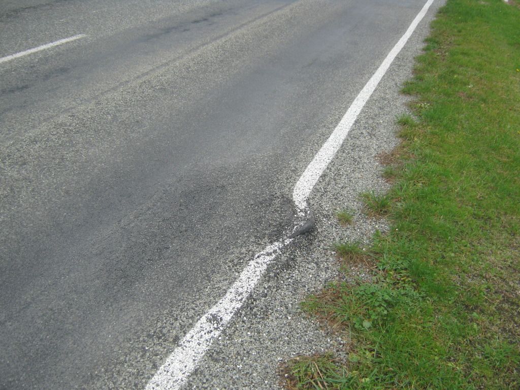
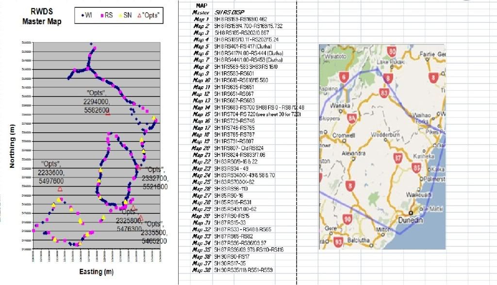
3. Each journey is taken at a time to remove the influence of other vehicles, and produces a brake specific fuel consumption value from defined road load. I've got all that data from NZS 260 series contor maps and RAMM data.

4. It continues along with the BOOT philosphy of Building, Owning, Operating, then Transferring engine and transmission combinations, without the overhead of dedicated shop dyno equipment. This means I can run the set-up as a cottage industry, which can be transferred anywhere in the world, but using local, proprietry parts.

All this can be replicated by a counterweighted power absorption dyno, so a dyno run could be made which is the same as, say, a Dunedin to Te Anau return journey. Since it covers considerable height change and extreme temperature variances, it's like a hyperbarmetric dynamometer

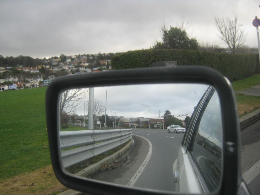
It basically electronically logs a pace vehicle or baseline vehicle, (in this case, my 205 hp 1998 Ford Explorer). The candiate engine, weather it be a cross flow, log, 2V or SOHC/DOHC in line six, is then put into either my 4 x4 Explorer or 2 wheel drive Mustang, and then driven over a 2500 mile test loop as part of the validation process. The loops include the Southland Te Anau in Fijorland National Park, the Otago and lower Canterbury road network, and has access to the Teretonga and Levels raceway (Invercargill and Timaru in the South island). Distance in these areas varies anwherer from above sea levels from 5 to 3100 feet. Grades go up to 12% for long grades, and steeper for short distances.

In addition, a 1/4 mile drag strip based on a closed down local aerodrome is run after the engine is run in. Then a cylinder check for surface texture and leakdown is made before bundling the engine off into a box to the new owner.

From this, fuel consumption, power, torque and real world drive characteristics can be determined before each engine combination is sold.
 
Some more Equipment arrived today for my tuning business, the E for engineering in XEC.

I use 10 main parts to tune my carb and efi vehicles , Clockwise from left, an Optilux 3763 timing light, a Projecta dt8308 multimeter, the Sun 023-168N dial back timing light, a bunch of US Holley 2300 carbs, the Spanish Bressell version of the Pinto engined 2000 cc Cortina 32/36 Weber carbs, a bunch of CR1000 data loggers from Scott Tech in Christchurch, a Sun Engine analyser, Brantz PC trip computer to measure distance, 64 bit Acer 5740G computer, and Alex Peppers awesome EEC4/EEC5 linking tools and software.


The remaining parts of my RWDS 2011 is practically complete, with the exception of a Ford cruise control for my Mustang. With that part locked in, I can load the throttle electronically to follow the pace set by the Explorer. In so doing, I can rate the required throttle postion to catch the Explorer. As long as I don't get caught behind too many 50 ton trucks carting 53 foot reefers of frozen fish to the nearest Port.

The RoadWarriorDyno System basically is a partial low to high load drive-ablity test, which validates air fuel ratios, advance, knock under load, knock when using low grade gas.

The calculated road load table is based on the Coastal Otago and Milford Highway topo and gps plots I've collected over the years. (a sample of Coastal Otago below). Each crimson RS is a 10 mile 'mile marker', and the blue readings are where I've intensively surveyed the road over the past 10 years since the R~S data base was set up as a green engineering kadet waving his Garmin globalnav back in the early noughtees. Back then, I called it RS 2002i, and spent late nights linking everything by co-ordinate geometery.The yellow SN are special control sites for coastdown readings so I can determine overall road load. I learned about the need to do this from the legandary Doug McMillan, who with the help of a road closure initated by a friendly official, drove a Honda VTEC CRX at 7 Mile Road, Oamaru, establishing 148.68 mph on 19 October 1997 with only 97 cubic inches, a class record. This was pivitol in me starting with a real world road load database.His figures in amagazine inspired me to do this. Him, and Burt Monroe..

dmacmillan.jpg


See latest info at http://www.hondata.com/hondata_speedwee ... lease.html, and http://www.hondatuningmagazine.com/feat ... ewall.html


The standard pace has been set by my cruise control equiped 98 Ford Explorer 4.0 SOHC.That's a heavy 4200 pound car with a smallish injected V6 engine, but great gearing and good power and torque. I've had an Alex Pepper system on order after some previous experience with it in my Explorer. I ordered the long 100 foot chord so I can hook it into my home computer. That allows me to do real time data playback, which can be duplicated at home.

The Explorer is travelling at 30 mph in urban area and 62 mph on the open road is the baseline pace vehicle, but it does so at times in adverse upgrades of in excess of 12%, and in altitude variations of 3000 feet yada yada yada, from sea level to summits at Lindis and Homer Tunnel. When the baseline was done, it was warm weather . In the Ex, rates of acceleration are set to its 250 lb-ft of turning force at 3000 rpm in a 5-speed 2 ton brick, but its drops mid 16 second quarter miles and is fast enough to make even a modified 2600 pound i-6 Mustang do a real work-out to catch up. I am able to match throttle position and fuel useage based on any idealised car combination. The required acceleration is matched against the required throttle for any given 200 or 250 cube engine in my 2600 pound Mustang. This allows me to map engine behaviour dynamically, record it, and then see if the engine is tuned properly. As I've said, I'm looking for
1.air fuel ratios,
2.advance,
3. knock under load,
4. knock when using low grade gas
but also what traditional "carburationists" call the
5.idle,
6.off idle,
7. progression/transition,
8.power circuit testing.
The last four are checked when you go to a mile marker, and copy an Explorer down load , taking first gear from a standing stop, slowly accelerating up the rev range. You then asses the quality of engine acceleration. The idea, suggested by Tony Patterson from SpeedTalk, is to see if the engine accelerates at a given rate on the off-idle circuit then picks up power when the main circuit comes in. In this case, you know the off-idle circuit is lean. If the engine looses power when the main circuit comes on you know it's lean and so on. This dude has a rather savage dislike of wide band a/f meters, but he is assessing the quality of performance in heavily saturated Pacific Grove California roads, where all the roads are hills and a mountain and traffic. Flat level streets, roads and highways don't exist. Much like here in parts of the South Island road network I drive.
 
Dean, your R&D posts for XEC engines are always awe inspiring, and most often just plain inspirational...Big>>> (y)

Now if XEC could develop a cerebral cortex interface for SD cards I might actually glean, and more importantly retain a bit more knowledge from them. :LOL:

But at the risk of stepping right off into the deep end here, what sensors, load measure methods or stats would one use for a 'real world' dyno such as this?
 
Deano has it down to a science, but you could replicate some of what he does with a straight stretch of road on a windless day.

On a pre-measured course you can measure the time it takes to coast down from one speed to another in neutral to determine frictional and aero drag. Then, if you know the weight of the car, with driver, you can accelerate from one speed to another, taking note of the engine rpm, and calculate wheel horsepower.

It's rough but it will get you close. If math is not your thing, there are on-board computers with accelerometers than can input your vehicle data and calculate for you.

But I'm just going to wait for Dean to put a card slot in my head.........
 
Road load at any point is just as per D McMillans example in NZ Hot Car in 1997:-

speed^3=(vehicle mass*gravity constant in ms-1*sintheta)*(flywheel hp-(drivetrain loss)-(rolling resistance)-(frontal area*wind tunnel drag coefficent))

Rule 5.

The hp required for an given speed is calculated below but you must know the tire size in mm, the cd and FA.

Formulae for power due to drag and drivetrain loss is then able to be worked out with ease.

cd is the drag factor. A Pinto is about 0.48, an intermediate Falcon (66-70) about 0.48, a Thunderbird 0.35, a Fox Mustang 0.44 or 0.36 if its got an SVO body kit. Early 60's XK Falcons are quite slippery before the T-bird roof get things messed up...more like 0.40 than the 0.48 or so of a 65 Falcon. Early Sprints were likely to have the least drag.

FA is the frontal area. Then multiply cd by Frontal Area Note that a Pinto is about 20.2 ft2, an early (late 60's) intermediate Torino/Fairlane is 24.2 ft2, and a fat bodied Mustang (71-73) about the same. A Fox Mustang is around 20.8 ft2. A Maverick could be as low as 21 ft2 for an early tudoor, or over 21.5 ft2 for a post 74 dodgem bumper number.

cd*FA *mph*mph*mph * 1.27
. 147733

Then add tire loss

mm*lb*mph*8
. 58 036 680


Rule 6:

The Hp loss or gain due to grade is

perpendicular rise/ horizontal run x lb x (mph/375)

This is the amount of power to add or subtract from the speed formula above if going up hill or down dale.

see viewtopic.php?f=5&t=31388 and viewtopic.php?f=5&t=6711

If the road is flat, only rolling resistance and vehicle acceleration within the length of road provided is an additional limit.

This can be postive, allowing, say, a 120 pound skier down a slick icey 60 degree slope to hit 155 mph with a 0.35 drag factor and a 3.5 sq ft frontal area.

Or negative, taking every one of a 12.5 ton trucks 120 hp trucks engine power to make it up a 12% gradient at 10 mph.

Aside from this, the formulae above allows top speed in mph to be calculated. I focus only on upslope and level road horsepower calcs on Coastal , and but calculate downslope items for a cross check but its all just plain hard to resolve down slope...its like a huge 2 ton flywheel on overrun.
 
Been out data logging in my Explorer.

I'm lucky to be able to hire my son out to drive while I do the baseline runs, so I can hook into the data without getting distracted.

At present, my baseline is a 3.73 gear Explorer 4.0 SOHC with 27" Mud and Snow tires with about 4400 pounds all up. Hp 205, torque 250 lb-ft. It would be like 147 hp and 180 lb-fts in my 200/55 390 tire Fox Mustang, two up. I can vary the effective diff ratio of 2.41 or 3.43 depending on if I lock the overdrive off.

I'm currently emulating the ideal waste spark ignition advance curve for a heavy 9.7:1 compression engine with port on port induction. I was cruising along a few days back in Te Anau, and found the advance curve was right up to 36.5 degrees at even 2000 rpm at 55 mph; a stunning amount of lead on a heavy high compression vehicle running on just 87 octane. I want the a level of safe advance which creates good fuel economy,and I can't get that unless I use real world situations.
 
Sorry about the bad footage of the first dummy run of my Explorer doing a four run average of a 16.72 second sea level standing quarter mile at 84.9 mph.


One up, with 1/4 tank, kerb mass 1.83 tons. Not bad for a 116 000 mile vehicle.

Gearing is 11% lower than stock, terminal speed was not 156 km/h but a still very impressive 84.9 mph. Found a secluded closed off area with a nominal 62 mph speed limit. 90 mph in NZ is instant loss of the right to drive, and maybee a 28 day car impound, so I've found a special section.

15.95 mph per 1000 rpm with 255/70 16 in 3rd
14.39 mph per 1000 rpm with 235 60 16 in 3rd, an effective reduction from the 3.73 diff ratio to 4.135, 10.8% lower geared. An indicated 156 km/h at 5900 rpm was really 84.9 mph.

My Explorer upshifts at 6000 rpm, not 6250 rpm. I was unable to get data logged runs, but am working on that (my daughter has my 32 bit computer for her hair dressing course, and my normal 64 bit computer doesn't run Alex Peppers CarCode program, darn it)
 
Frankenstang":32ispw2z said:
what sensors, load measure methods or stats would one use for a 'real world' dyno such as this?

In Alex Peppers program, there is facility to use 103 ratiosand out puts, often using auxilary gear only available by Ford technicians. I can only get 12 of those 103 potential graphs. They are:-

1.Engine temperature
2.TPS setting as a percentage
3.MAF flow rate
4.Intake absolute temperature
5.RPM
6.Spark advance

7.gear position8.barametric pressure(If conditions are stable). If you have the extra gear, 8.lambda sensor A/F ratio, 9.back pressure. 10. Piezo electric knock sensor reading.

The basic road load TPS % is important, because you can copy a fixed load, and then test your engines response to lean cruising, mean best torque ignition settings, and all that stuff. I use GIS to overlay my total distance travelled to form a velocity time graph displacement measured by a Brantz meter. When good constant road load calcs can be made, I can form an image of the EFI programming

Armed with this, an old Mustang with some of this gear can then be tuned with modern EFI stratergies to lean off the mixture and richen it when it has to be rich. Ignition can be mapped top suit.


For ackward calibrations, say Offy or Triple Weber installations, the variance in air fuel ratio and advance can be tailored to suit mild road load conditions on the road circuit, and then cross checked on a dyno.
 
I'm downloading a couple of YouTube video for files for your benefit. The first is a video of my basic data logger set up, as put together for my Road Roughness Project.

http://youtu.be/gysEPJ9EHMA

The second is a Night Riding profile of the XEC Road Warrior Dyno System in Dunedin August 2012, while I was recaliabrating the road roughness components.
http://youtu.be/_B9B_en_Hdo

It uses the same set up depending on what my job is...my job as a roading technician puts me out measuring road roughness or just auditing road networks with my visual data recognition package.

One day, being chased by white Right Hand Drive SN95 Mustang Cobras


.... the next data logging road defects and pot holes.


(Not that I find many of those down here in the South Island)

My data logger

 
Back
Top