Henry Yunicks Red Hot Vapor Engine Re-Creation

I also forgot to mention that I just got done building a 3D printer so I can print mockup parts and casting negatives to cast parts such as the piston. The piston is a unique deflector type which I will be making from aluminum bronze.

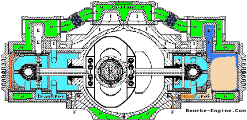
The crankshaft will be a "tunnel style" crankshaft, the crankpin/journal bearings will use one piece superposed triple slipper bearings. That is, a solid bronze bearing in a bearing in a bearing. The main bearings will have a total of four main bearings for two cylinders. Two 4" diameter NK105 disc type roller bearings, and two 1.25" conventional pressurized plain bearings.

The objective goals of this engine project is to create and engine with a greater than 75% thermal efficiency (I'm shooting for at least 80%) yet be simpler in design with less moving parts than a lister engine, last at least 3 million miles before an overhaul is needed, and no ignition system necessary at all. Only a glow plug for startup on a cold day. Its designed to be able to be top overhauled in less than 5 minutes and the crankcase overhaul in less than 10 minutes. If the crankshaft breaks it will break the crankpin which is a 30 dollar part because the crankshaft is made of three pieces which allows the use of solid bearings and other unique bearing designs as well as easy changeouts. The cylinders pull off like a Harley V-twin. And my long term goal is to integrate flanges into the block which will allow the engine, with crankshaft plates to replace an output crankdisk with a joining crankdisk, to bolt together front to back to increase engine length so that three universal mass manufactured displacements, a 3 CID, 30 CID, and 200 CID, can cover everything from weed wackers to ships, trains, planes and everything in between.
unknown.png

unknown.png


If you guys here need anything 3D printed let me know.
 
DeltaV":2qkfom5b said:
Exhaust and intake ports use slide valves like an old detroit diesel. There are four exhaust ports, each 5.66" in diameter
There are six intake ports, two are .626" and four are .25" diameter.
Can you help me visualize where the slide valves are located and how they are activated?
Thanks
 
The reason I wasn't sure what you meant by slide valves is because that is known to me as "piston porting"
Slide valves were used on some early 4 stroke engines instead of poppet valves.
Communications is a wonderful thing.

What are you using for a counter weight?
What is the height of the intake port where air is taken into the bottom chamber (from the bottom to the top of the port)?
Why the addition of the Roots Supercharger?

OK I'll stop now with three questions. :D
 
Counter weight will be external on the flywheel. The crankcase is so small there is no room for an internal counterweight. Adding one would lengthen the crankpin/journal pin and would make the crankshaft weaker.
The supercharger is a homogenizer. Each cylinder has its own turbo, but we want to make sure that the charge homogenizes before it starts diverting to each cylinder.
Below is what the intake and exhaust ports look like. Intake charge goes behind the piston, and is then transferred to the top of the piston via identical ports on the other side.
unknown.png
 
Thank you for the more detailed pictures of the ports.
Gives me a much better understanding of your overall engine design

Anytime a supercharger is added to a system (Especially a Roots) the system efficiency is lowered.
Yes, In order to get 60 lbs of boost a compound system is needed, either supercharger/turbocharger or turbocharger/turbocharger.
A turbocharger is much better as an homogenizer so why not use a compound turbo setup?
 
:D very compact and so few parts it's very interesting! So what kind of power potential does these small engines have? Any idea as to the operational economy as in your proposed home electrical power source compared to the grid type costs? (y) :nod:
 
Power potential is very high. This 30 CID 0.5 liter engine, when naturally aspirated, should be able to produce at least 160 horsepower. Most engine try to avoid "knock" "ping" and "detonation" I've designed this engine to embrace it as a part of its detonation cycle. This means we can run compression ratio's as high and even higher than 30 to 1. Assuming you have natural gas (I don't, personally) and assuming the engines thermal efficiency is only 50% (other similar engines built have had efficiency's as high as 81%) and assuming you're paying 9 cents per kilowatt hour, the cost would be about 7% cheaper than the grid. Now, if the engine is 75% efficient and you're paying 12 cents per KWH the engine will slash your electric bill by over 50%
 
I might just use only a turbo as a homogenizer. Depends ultimately on what this engine ends up being dropped in. For stationary power generation and testing its either going to be NA or turboe'd.
 
Excellent I do have natural gas here and the electric rates are very high too. I will be watching with great interest on your progress, good luck on the build. :nod: (y)
 
The intake port has two .626" holes which represent a 120 degree port duration starting from 60* BTDC to 60* ATDC.

I'm assuming the piston rings do not traverse across this port.
If that is the case, instead of two holes could you just open the port to a .626" slot as wide as the port opening?

I would advise the use of a single turbocharger to service both cylinders for the following reason.
Turbochargers work best if the airflow in near constant.

Since this engine has a 120 degree intake port window means there is 240 degrees when the door is shut and pressure builds before the piston opens the port again.
That is not a problem if there is a high volume intake system that contains an intercooler but this non-intercooler intake system has very little volume and the pressure will certainly vary.

Normally as the pressure goes high and the airflow drops a turbocharger can be driven into the surge zone and over rev leading to damage.
In this case the engine rpm is high enough that the inertia of the turbocharger wheel will not respond fast enough to the frequency of the pressure spikes however the turbo will still be operating across a wide zone of low efficiencies.

If the turbocharger services both cylinders then the total intake port duration is 240 degrees with only a 120 degrees of stop duration.
Still not ideal but much better.
There is a fix that will not only make the engine more turbocharger compatible but will also produce a very low rpm high torque engine.
I will save that for another discussion because it has a lengthy explanation.
 
Interesting!
As far as the port holes goes, I'm basing them off the original blueprints from 80+ years ago. Legend has it that the engine is incredibly sensitive to port sizing. HOWEVER, after I get the first one made I will start experimenting a lot with different port sizes and shapes. Good to know that a single turbo would be better for this application! That makes the job a whole lot easier.

A low RPM high torque engine intrigues me very much. If you get time I'd LOVE to hear how you'd approach such a design.
 
DeltaV":2qaajrgl said:
Legend has it that the engine is incredibly sensitive to port sizing
Yes and especially if using a carburetor and trying to maintain detonation without a spark plug.
It is not the static compression ratio (SCR) that supports detonation, it is the Dynamic compression ratio. (DCR) that determine the cylinder pressure.
On a piston port 2 cycle engine the DCR is determined by the amount of air fill in the chamber below the piston. The longer the intake port duration is, the higher the engine rpm has to be before the DCR is high enough for detonation because of the intake port reversion after TDC.
When using a carburetor for control, when the throttle position is closed for low or no load conditions the cylinder pressure drops, and combined with a long intake duration the engine may not have enough cylinder pressure to maintain detonation mode especially at lower rpm.

As you already know by your plans for a “Cracking Unit”, the Bourke engine running in pulse detonation mode should not have a throttle plate and is best controlled solely by the amount of fuel so it will always have a very high cylinder pressure.
You will also find that the engine will run at a lower rpm.

On the other hand if the intake port is too small with a short duration the high rpm cylinder pressure will suffer. That is the reason I suggested changing the intake port from two .626” holes to a .626” slot.
The port timing doesn’t change but the port area doubles for increased chamber fill at higher rpm.

Looking at the piston port design, as the piston travels from the bottom of the cylinder it creates a vacuum in the lower chamber that is used to draw in the intake charge once the piston skirt clears the intake port. Once the piston is at TDC the intake port is still open. Above a certain rpm there is enough intake velocity to prevent intake charge reversion as the piston moves down from TDC. Below that rpm point the downward moving piston pumps some of the intake charge out of the lower chamber till the piston skirt closes the intake port. This is where low rpm torque is lost.

The second thing to consider is the high vacuum created in the lower chamber works against the piston motion and is considered a pumping loss which lowers engine efficiency.

Third. As piston ring seal decreases with age any resulting blowby reduces the lower chamber vacuum and lowers the intake volume.

One solution would be to have an induction system where the intake port is open from the time the piston leaves BDC and closes right after the piston reaches TDC.
The intake duration would be a full 180 degrees, the vacuum level would be low reducing the pumping losses for a more efficient engine and with the closing point around TDC (eliminating port reversion) the low rpm engine response would be exceptional.

What I envision is a rotary shaft induction that turns at half the crankshaft rotation.
The shaft would have two slots 180 degrees apart the same size as the intake port.
Each slot would need to be 45 degrees wide and timed so the leading edge of the slot begins to uncover the intake port as the piston leaves BDC and the trailing edge closes the intake port at TDC.
The intake port no longer needs to be at the top of the lower chamber and can be located further away from the exhaust port.

I did a similar conversion in 1976 where I needed a very high torque low rpm 2 cycle engine.
I started with a piston port engine that had very conservative porting and three flywheels.
On this application I used a twin bank, 12 reed valve setup. The reeds where small and made from fiberglass so they were very responsive.
I drilled two rows of ½” holes in the piston skirt to expose the intake port to the lower chamber during the full piston travel.
I now had a full 180 degrees of intake duration with the reed valve shutting off the intake port after TDC for a full 180 degrees of compression for transfer.

Without any other changes the DCR increased to the point where I could no longer use pump gas without detonation and required 100+ octane racing gas.
High torque was available from an idle and was much more than what I expected.
 
Interesting, and I fully agree with your assessment! 'm trying to minimize the amount of moving parts as much as possible, and a rotating valvetrain though effective, increases cost and complexity. Perhaps instead of a rotating valve I can simply move the intake ports to the bottom of the chamber and install a reed valve as a one way check valve to prevent the charge from reversing? So here's what I'm thinking, I'll leave the original ports in their location and add a set of ports at the bottom with a reed valve. This way I can block off one set of ports, or the other, or leave both open, and functional and see what runs best.
 
Sounds like a plan!
My hopes is that you can get the engine to idle about 650 rpm without an ignition system and produce massive amounts of torque from idle on up.

As you already know this would be needed for vehicle use where the engine needs to operate over a wide rpm range however it would also make the engine eligible to operate a highly efficient inverter generator where the engine runs only as fast as needed to supply the power requested by the load.
I have an inverter generator.

I noticed a raised floor in the lower chamber to increased the transfer charge pressure.
What is the compression ratio of the lower chamber?

Will you be testing the engine using a dyno?

Just a side note
The reason for the rotory valve induction was that I felt it would have better longevity than a reed valve system.
Don't change a thing! I'm just sharing my thoughts.
The reed valve is the easiest way to get the project rolling for evaluation.

Thanks again for sharing this project.
 
I honestly have no idea what the compression ratio is on the underside of the piston. The geometry is so complex that only a liquid displacement test could determine that with any amount of accuracy. If the compression ratio is particdularly high, what I might even be able to do is modify the combustion chambers to be of a cross flow type and redesign the underside of the pistons underside so that both the underside and top of piston are combustion chambers! That's an experiment for the far off future! After some careful thought I figured out how to modify the bushing plate to force an intake charge directly to the underside of the piston. I'll leave the current ports and add a large slot to the bushing plate for maximum intake paths.

On another note, I'm considering on making the pistons out of aluminum-bronze for reduction in coefficient of friction, increase max temperature resistance, and increased strength. Thoughts?

As far as valves goes, if I ever get this engine into a mass production style run I'll use valvular conduit that will be cast into the intake manifod. That will give you a solid state one piece check valve with no moving parts at all. Unfortunately for this machined prototype valvular conduit is far too geometrically complex.
 
Intake port through the bushing plate will let you leave the piston skirt as is. Good Idea!

Aluminum bronze is a bearing material with a melting point above 1800* F and dissipates heat well.
It is cast so not sure how brittle it is?

A valvular conduit is a dynamic component which requires flow in the reverse channels to create resistance to flow in the forward channels so there is still plenty of leakage especially if it is short. Nice concept though.

I didn't mention this earlier but another reason for the rotary shaft induction is it can be used to vary the engines DCR or cylinder pressure if the need arises somewhere in the future. Just not now.
 
Just wanted to give everyone here some updates.
A local blacksmith and I bored out two inline 6's and preparing them for a quick and simple rebuild. He's going to be reducing compression ratio on his so he can burn diesel and motor oil and My F350 was converted to run on propane so I'll be using a 13:1 ratio.

As far as the Bourke engine goes, I've invested in a 3D printer and my first lathe so I've redesigned the engine to use mostly castings. This smaller engine is a 49cc prototype that should produce 15 horsepower or more. I have the molds 3D printing right now for investment casting the engine.
Below are some pictures.
20190324_134820.jpg

20190324_191341.jpg


Also because I didn't have a piece of steel thick enough for the yoke for the prototype engine we'll be hammer forging a damascus yoke. Samurai sword crankcase! Its a combination of A500 and spring steel. Not the best but its convenient and what we have on hand.
20190324_202538.jpg


And of course here's some pictures of the new model.
unknown.png

Those four allen wrenches are all thats required to completely overhaul the entire engine.

The first thing I'm going to do once the engine is complete is couple it to a generator to get some dyno numbers and go off grid. There are so many awesome classic vehicles that just need an engine swap to get them going again. Too low geared for good highway cruising. With a safe RPM of 30k this engine will breathe new life into all the vintage vehicles laying around farms across the country.

And of course I'll need to build the thermal cracker for it. That will be suitable for any engine to use.
 
It looks like the intake port is at the bottom of the lower chamber possibly going through the bushing plate?
 
Back
Top