All Small Six 68 small log head porting

This relates to all small sixes
Yes, there should be a spot.
It's my opinion that 6 individual pieces would be less waste, cheaper, easier, lighter for the racer in me, and hole spacing does not matter. no clearance issues. Just line up the shims just before you torque it down hard. If i was doing it, I would measure the head base add some fudge factors, drill 6 holes, same size as bolt along the material, put bolt in rocker shaft ass. stand/pedestal over one hole and draw around giving about 1/8'' extra, cut out with fine band saw, hack saw, jig saw clamped down in vice and use like a band saw, file flat, done. Do not forget last stand hole needs to worked to be square, file, dremal etc. for oil flow.
 
Last edited:
I am curious how much the compressed thickness finally installed will be, maybe I'll never know (don't know how I could possibly measure that...).
Set up a Dial Indicator on the head with gasket installed but not torqued down and Zero the Dial Indicator. Then Torque down the Head Bolts and see how much the Dial moves, that should give you some idea of how much crush there is of the installed Head Gasket. Good luck.
 
One more question for the community:
The wear pattern on my valves dtems with the 1.65 RAU shaft rockers. The pattern is not centered, leaning more to the shaft side.

Can I leave it as it is, or should it be corrected (shimming under shaft mounts/milling shaft mounts)?
The rockers have a roller tip...

A question regarding the shim washers to put under the rocker shaft mounts for better geometry:

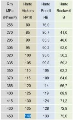
Is a hardness of 140HV (Vickers) sufficient for the hardened washers or should I look for something harder?
I was initially thinking of AN970-6 washers, but they have a hardness of only 40B (Rockwell)…

hardness table.jpg
 
The washer is simply an extension of the cylinder heads cast iron rocker towers so there is no need to have it extra hard.
The main concern is flatness and wide enough to completely cover the surface area of the tower or the bottom of the pedestal
I don't see a problem with the AN970-6 washer as long as it is wide enough to cover.
 
I haven't tested yet. I ordered the AN970-6 washers with a thickness of .063" an some metric washers with a thickness of .118".
Will try it again when installing the head and keep you all up to date what worked for my application...
 
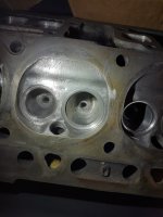
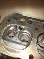
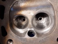
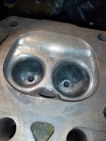
The head is almost finished now. Since my machine shop left a little ridge on the inside when the installed the new hardened seats (see below), I had to blend the bowl again into the 3 angle seat. Throats are now 1.5" and 1.25", that means maximum of 91% throat to valve ratio with the standard valves.

Last thing to do is to shave the head, which I can do mid january. The plan is to achieve 47cc chambers for around 9.02:1 static compression ratio and 8.2:1 dynamic compression ratio.

Attached is also a picture when I disassembled the head...

before porting.jpgmachining 1.jpgmachining 2.jpg
 
After quite some time I have some updates on my progress.
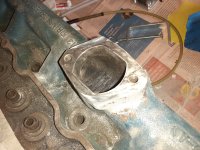
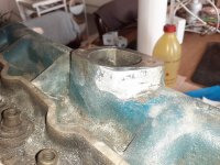
The head is finally machined and all I need to do is make the gasket surface on the enlarged log hole bigger so I don't get any vacuum leaks. I started to add some JB weld around the sides where the metal was thinnest after enlarging the hole (new opening has the same cross section surface as the 1.75" opening of the big log heads). I will have to play around with some more JB weld to make the top surface flush and make a custom gasket (I have som felpro material for that).

20231016_172201.jpg20231016_172152.jpg

In the picture is also visible that I enlarged the radius from the opening into the runners quite a bit to around 1/2" as suggested from Bubba!
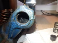
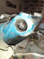
And I tried to round the sharp corners on the runners 1 and 6, I did the best I could and I think the are a little bit rounder (left is original, right is after some grinding with a round stone):

20210822_183946.jpg20231016_172221.jpg
 
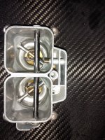
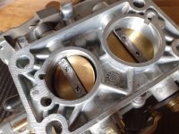
My Weber 32/36 also got some love.
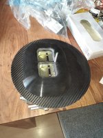
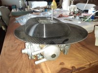
First I designed a large stub stack and 3D printed it to smoothen the incoming air.
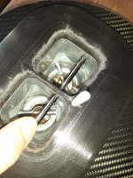
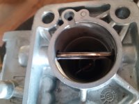
The choke plates and throttle shaft blades got smaller screws (with red loctite) and the overhanging threads ground flush (throttle plates got also a little knive edging, but barely).

20231016_172341.jpg20231016_172403.jpg
20231016_172414.jpg20231016_172547.jpg

I removed all casting flash and ridges in the venturis and on the auxiliary venturis.
Also the accelerator pump jet on the secundary side got ground of since it wasn't drilled anyways...

20231016_172704.jpg20231016_172512.jpg

This is not really "head porting" but I see it as air flow enhancement so I thougt I post it here also.
 
glad 2 C that 'drop base' ac housing bottom.
Hope it avoids a "tight" hood. (1st 2 pic in #130, etc)
 
Yes Chad, I mocked it all up with the head on the block, with the standard aur filter adapted to mount onto the carb plate I have enough clearance to the hood in my 68 Mustang. The air cleaner is also offset to the middle of the car, this way I could fit the threaded rod and also don't bump into the hood struds
 
There's a lot of good info in this thread. I plan on pulling my head this winter to go through it. Lots to do....
 
Good update.
Thats not so good the machinist gave back to you with ridges at the valve seats
 
Yes, but I tried my best to eliminate the ridges, the dyno will show if I managed to do it sufficiently ;)
 
Last edited:
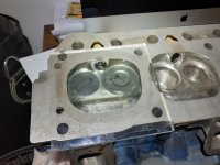
I measured the chambers after shaving the head .0275" (0.7mm).

chamber cc.jpg

Initially I got 51cc chambers.
Unshrouding the valves increased the chamber volume to 53.5cc.
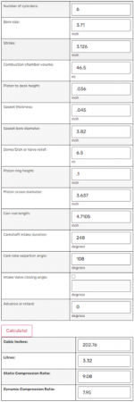
After shaving the head .0275" the chambers have a final volume of ~46.5cc.

With a Mahle head gasket and my Isky Mile-A-Mor cam that should result in a static compression ratio of 9.08:1 and a dynamic compression ratio of 7.95:1.
I think I will not try to get higher on the DCR as I would like to use regular pump gas...

CR and DCR.png
 
sawa e85 sign on a local pump on Fri...
needs such on all MA pumps in our state.
Wish bubs was here to pipe in abt AZ & Cali...
 
Last edited:
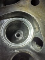
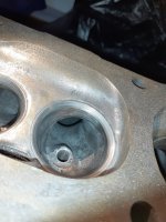
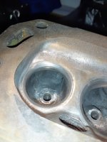
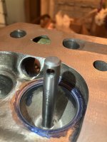
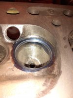
I added another 80° angle to the 3 angle valve job on the intake seats to blend the seat a little better into the bowl.
Hopefully that improves low lift flow also.

bigger grey ring = seat
smaller grey ring below = 80° seat blend

80 degree seat.jpg80 degree seat 2.jpg
 
Last edited:
Back
Top