You are using an out of date browser. It may not display this or other websites correctly.
You should upgrade or use an alternative browser.
You should upgrade or use an alternative browser.
All Small Six Installing and Degreeing Camshaft - 1983 200lm
- Thread starter Dr_Dan_WWW
- Start date
This relates to all small sixes
Yes, I do agree and the dial indicator, but it my understanding the wheel is fastened to the crank turning tool and it has about 1.5 degrees of slop/play so I believe there could be about .75 degrees of Error. It is not enough to worry about, but it is there.The accuracy is in the piston stop, degree wheel and the pointer. As long as the degree wheel isn't moving the slop in the crank turning tool means nothing
Thank you pmuller9.
I believe I need to re-find TDC and start over.
I believe I need to re-find TDC and start over.
I wanted to show my new TDC findings. Here's the video. Tell me what you think, but I believe this is tight. I attribute any movement back and forth due to the connecting rod bearings clearance or bearing slack - as noted back in posts #86-88. Each time I reverse the crank the bearing reveals some gap. An 18 inch degree wheel may really amplify this clearance gap.
View attachment Bronco 1983 engine TDC exhaust cam degree 1 IMG_7373.MOV
View attachment Bronco 1983 engine TDC exhaust cam degree 1 IMG_7373.MOV
Ok, it looks very good.
Proceed.
After you check the exhaust lobe, go back and check the intake lobe.
Then I will show you what to do with the two .050" exhaust readings and the two .050" intake readings.
Also measure the exhaust lobe lift and the intake lobe lift.
Proceed.
After you check the exhaust lobe, go back and check the intake lobe.
Then I will show you what to do with the two .050" exhaust readings and the two .050" intake readings.
Also measure the exhaust lobe lift and the intake lobe lift.
Last edited:
Okay sounds good.
"Also measure the exhaust lobe lift and the intake lobe lift."
By this you mean measure the actual distance the lifter travels?
"Also measure the exhaust lobe lift and the intake lobe lift."
By this you mean measure the actual distance the lifter travels?
Yes I’ve been watching you go by the reading several times in the videos and it looks close.
I just recorded the exhaust lobe measurements. I will post the video and then I can go back and measure the max lift on the exhaust.Just need you to actually stop at max lifter lift while you are moving the degree wheel for the other reading and record the lobe lift.
Here's my exhaust lobe measurements. Apologies for the longer video.
View attachment Bronco 1983 engine cam degree exhaust +2 2 IMG_7374.MOV
Here are the raw numbers at .050"
1st .050: 144 (or 36) ATDC. I believe this is a number we want.
2nd .050: 145 (or 35)
3rd .050: 78 (or 102)
4th .050: 38 (or 42) After BDC. I believe this is the number we want to use.
5th .050: 8 degrees. The dial indicator stopped turning.
Math: I attempted to calculate duration but I am confused at this point. Any help is greatly appreciated. Thank you.
Exhaust lifter travel distance: .275
I will measure the intake lifter travel after we confirm the cam timing of the exhaust.
I will measure the intake lifter travel after we confirm the cam timing of the exhaust.
Your numbers are: Open at 36 BBDC and close at 8 degrees BTDC.Here are the raw numbers at .050"
1st .050: 144 (or 36) ATDC. I believe this is a number we want.
2nd .050: 145 (or 35)
3rd .050: 78 (or 102)
4th .050: 38 (or 42) After BDC. I believe this is the number we want to use.
5th .050: 8 degrees. The dial indicator stopped turning.
Math: I attempted to calculate duration but I am confused at this point. Any help is greatly appreciated. Thank you.
Cam card shows 36.5 and 7.5
180 - 8 = 172
172 + 36 = 208 degrees .050" duration.
Lobe center = 208/2 + 8 = 112 BTDC which is correct for the exhaust lobe center.
If the intake lobe center is advanced 4 degrees from 108 which puts it at 104, the exhaust lobe center moves 4 degrees the other way from 108 which is 112 degrees.
The cam card shows the lobe lift at .280" and you measured .275"
Close enough.
If you check the intake lobe center next it should be very close to correct.
Last edited:
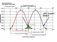
After you do the math, pmuller9, it all makes sense to me. I am picturing the Cam Timing Points graph, ".050 Duration Method." The two measure points are very near the beginning and the end of the graph:

With my lack of experience, every time the dial indicator passes over .050 I wonder/doubt if I missed the correct measurement. Of course by the end then I have a bunch of ".050 numbers," about 10 measurements to be exact. Only two .050 measurements are important - the one's with the arrows, which I believe pmuller9 drew on the graph image. The graph shows in blue text "Intake Duration @.050" But the total travel distance is close to .500 to .600 inches. Red text shows "Exhaust Duration @ 0.050 inches."
I hope my inexperience with all this camshaft lobe duration (degreeing) and y'alls expertise helps other noobs on FordSix.com know that it is possible to rebuild an inline 6 200 without being an expert. I sure do appreciate the forum. It is truly fun and challenging.
I will proceed to measure the intake lobe duration again. And I will measure the travel distance of the intake lobe. I will post my results.
I rechecked the intake duration and here's what I got:
I open at 0 degrees.
I close at 27 degrees.
180+27=207. Degree of duration on the cam card is 209.
207/2=103.5 Centerline on the cam card is 104.
I went back and slowed/stopped the video to capture the intake lobe height or lifter travel distance and the video showed 0.274" Cam card calls for 280.
How'd I do?
You did a great job!How'd I do?
You are done with the cam installation.
Once you get the harmonic balancer on, check the TDC timing mark to see if it corresponds with the piston at TDC.
My gratitude to pmuller9 and everyone else who guided me through this cam install and degreeing.
I really do daydream about stomping on the Bronco's gas pedal and the thing hopping right to it. I can't wait to hear the slightly loppy idle ( I think). Of course also I lay in bed imagining the worst: turning it over for the first time and hearing the crunch of push rods and valves. We shall see.
I will start another post for the next step. Here's where the engine rebuild is at the moment.
It's time to focus on the cylinder head - again.
The 1983 head has a valve job done by Noland's Head Shop here in KC. Things done; magnfluxed, new guides, three-way valve job, new seats, new valves, etc. I spent a long time porting the head and did an "E for effort" job. I have the 3/4 exhaust port divider from Vintage Inlines.
Bubba22349 has been my Jedi all the way through that process. Bubba helped me spec the rebuild. He truly is the Guru. So I feel good about the head. Immediately up next is the milling of the head. The head is at the shop to me milled 0.030" to get the quench down to 54cc. Bubba again took me through calculating exactly what needs to be done to get the Dynamic Compression Ratio where we need it. But he wants me to verify things haven't changed with the cam work we just did. I will be on that immediately before the head is milled.
I have a RAU 1.6 adjustable rocker arm. The Howard cam kit came with new hydraulic lifters. One of the big unknowns at this time is pushrod length. I got new ball and cup pushrods with the cam. But they may be too long with all the decking and milling. I will have to check the push rods.
I have plenty to work on.
Thank you one more time for all the help. I am very excited to keep the Inline 6 engine enthusiasm alive. With my '66 Bronco I may not be hotrodding like you guys. But as the man told me, "If that Bronco were meant to go fast it wouldn't be shaped like a brick."
You will know when the timing cover and pointer is in place with the damper installed and you check tdc with the head off. I think that the bolt on pointer has to be on before the damper. Post 68 shows the bolt on pointer.
Last edited:
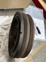
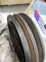
That one looks like the elastomer is coming out of it.Okay. Which harmonic balancer mark is supposed to match up with the piston at TDC? (photos) Notch: View attachment 11419 Slit mark: View attachment 11420
Similar threads
All Small Six
Camshaft Degree Troubleshooting Help
- Replies
- 30
- Views
- 2K
All Small Six
Camshaft break in and transmission fluid levels
- Replies
- 4
- Views
- 492
All Small Six
Cam degree off?
- Replies
- 25
- Views
- 1K
All Small Six
Oil Pan Pick Up Problem for '83 200lm in '66 Bronco
- Replies
- 11
- Views
- 614
- Replies
- 3
- Views
- 460


