You are using an out of date browser. It may not display this or other websites correctly.
You should upgrade or use an alternative browser.
You should upgrade or use an alternative browser.
This will be fun
- Thread starter Ikosix
- Start date
So here’s what I had done on the head. It was cleaned and checked for cracks. Milled flat on the mating surface. He increased the size to 1.60/1.94. The guides were cut for viton seals.
Hardened seats and all the valves were faced. The stud towers were drilled and tapped. I gave him a spring retainer and the valves and he went through them and set the installed height for each valve then numbered them for me. I used the die grinder beforehand in the bowl area. He installed two of the rocker studs. I gave him a pair for reference while drilling them out. Before I masked it off I put a rocker on one of those installed studs to see if the cover would fit and it seems like there’s about a 3/8” gap. I’ll double check this weekend after I paint.
Hardened seats and all the valves were faced. The stud towers were drilled and tapped. I gave him a spring retainer and the valves and he went through them and set the installed height for each valve then numbered them for me. I used the die grinder beforehand in the bowl area. He installed two of the rocker studs. I gave him a pair for reference while drilling them out. Before I masked it off I put a rocker on one of those installed studs to see if the cover would fit and it seems like there’s about a 3/8” gap. I’ll double check this weekend after I paint.


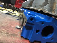

You will want to counter sink the holes for the studs a little.They are ARP 134-7123
There’s a small gap. I’m waiting on the sealant for final installation. They are in there hand tight.
It is important the the stud tightens down on the shoulder under the hex without binding on the last thread under the hex.
Any radius at the last thread can split a piece off the stud tower.
Every thing else looks great!
Were the towers lowered any?

You only need to torque the studs to 40 lbs with a good sealant.
The 640 Loctite is a cylindrical sealant and retainer meant for high heat and vibration applications.
You can use the bottom of the EFI cover and the top of the "Powered by Ford" cover to make one tall cover.
The 640 Loctite is a cylindrical sealant and retainer meant for high heat and vibration applications.
You can use the bottom of the EFI cover and the top of the "Powered by Ford" cover to make one tall cover.
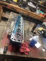
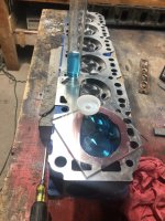
Here’s where I’m at in the process. Pmuller9 I did like you suggested and reamed the rocker stud tower holes so the studs sit flat on top. We installed the valve springs to 1.7”. This afternoon I flipped it over and measured the chambers and came up with 74ccs each. I’m guessing the next thing to do is get the block to the shop and see what needs to be done on the cylinders and deck? Then I can call and get pistons ordered?
Opinions?
I haven’t pulled the block apart yet
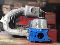
Also I was able to get cncdudes very last valve cover spacer!! Thanks for that. I mocked up the intakes to the head and there was almost an inch of space so I think it’ll work great
Opinions?
I haven’t pulled the block apart yet
Also I was able to get cncdudes very last valve cover spacer!! Thanks for that. I mocked up the intakes to the head and there was almost an inch of space so I think it’ll work great
Attachments
Everything looks great.
For my own curiosity, How much was shaved off the head surface?
Do you have the Crower Cam?
Get the block done and get the connecting rods resized with ARP bolts.
Then you can measure the block deck height and the finished rod length to get your piston pin height.
Get the crankshaft done also so you can order rod, main and cam bearings.
Last edited:
The shop gets the bare block, crankshaft and connecting rods.
Most of the time you take the block apart and remove the freeze plugs and oil passage plugs paying very careful attention to where each oil plug came from. Also carefully remove sensors paying attention which hole each was in. Take pictures if needed.
Take the time to prepare marked ziploc bags so as you remove each set of small bolts from covers and other parts they are identified in a bag.
Remove the rod and piston assembly being careful not to let the rod bolts hit the crankshaft journal as you push the pistons out the top.
Tape the connecting rod bolt threads or use plastic tubing.
Remove the rod bearings and put the rod cap back on the same direction it came off.
The shop will need to press the piston pins out of the connecting rods to remove the pistons.
Remove the main bearings and put the main caps back on with the cap bolts snug.
Remove the camshaft with the gear in place for now.
You can leave the cam bearings in.
Then you can clean the block with a good degreaser, scrape gaskets off and begin your own inspection.
Look for sand/iron lumps in the crankcase surfaces and inside corners. If you find any then grind them away.
Remove all casting flash especially in the cam tunnel.
Finally radius all edges in and outside the block.
 fordsix.com
fordsix.com
fordsix.com
Most of the time you take the block apart and remove the freeze plugs and oil passage plugs paying very careful attention to where each oil plug came from. Also carefully remove sensors paying attention which hole each was in. Take pictures if needed.
Take the time to prepare marked ziploc bags so as you remove each set of small bolts from covers and other parts they are identified in a bag.
Remove the rod and piston assembly being careful not to let the rod bolts hit the crankshaft journal as you push the pistons out the top.
Tape the connecting rod bolt threads or use plastic tubing.
Remove the rod bearings and put the rod cap back on the same direction it came off.
The shop will need to press the piston pins out of the connecting rods to remove the pistons.
Remove the main bearings and put the main caps back on with the cap bolts snug.
Remove the camshaft with the gear in place for now.
You can leave the cam bearings in.
Then you can clean the block with a good degreaser, scrape gaskets off and begin your own inspection.
Look for sand/iron lumps in the crankcase surfaces and inside corners. If you find any then grind them away.
Remove all casting flash especially in the cam tunnel.
Finally radius all edges in and outside the block.
All Small Six - The 'Ideal' 200 Built By Committee
I picked up a 1978 200 a while ago, for no other purpose other than I was bored and needed a road-trip to New Jersey. The head has been cleaned and no cracks found. It is sitting on a shelf, partially pocket ported ... (for sale soon) The block has not been inspected yet. It is sitting on an...
Last edited: