View attachment 11706
Nice custom tank! Where did you get it from? One thing, be sure that vent on the second chamber is good and open, or that side won't fill as fast as the gas is pumped in.
You are using an out of date browser. It may not display this or other websites correctly.
You should upgrade or use an alternative browser.
You should upgrade or use an alternative browser.
'76 F250 Turbo Build
- Thread starter jgavac
- Start date
Nice custom tank! Where did you get it from? One thing, be sure that vent on the second chamber is good and open, or that side won't fill as fast as the gas is pumped in
Thanks! It came from a company called Aero Tanks in California. It cost a pretty penny, but AFAIK they are the only ones out there making a tank that fits in the narrow frame of the highboys.
That's a nice tank! There is a company Soulless Innovations in MS that is making rear mount tanks for the narrow frame 67-72 F100s, but they say they will not fit long beds, unfortunately. I do believe they will fit the 67-77 F250 crews, including 4x4, since they are narrow frame short beds as well.Thanks! It came from a company called Aero Tanks in California. It cost a pretty penny, but AFAIK they are the only ones out there making a tank that fits in the narrow frame of the highboys.
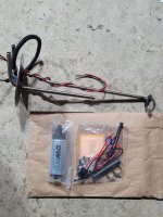
Couple updates! Picked up a deatschwerks 255 lph pump for the new fuel tank
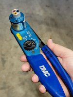
And also finally found a good deal on a DMC crimper and indexer, so I'm running low on excuses to put off wiring
Couple issues I am having at the moment - in having a hard time finding anyone in my area who is able to make a custom fuel rail from extrusion, I'm wondering if at this point I just need to talk with a dedicated machine shop (not an engine/auto machine shop) since it needs off axis holes for the injectors.
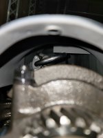
The other thing I'm dealing with right now is the oil pan not fitting with the pickup tube. I've got the pickup support pressed down as far as it will go on the main stud before it changes to the larger thread, but it's still bottoming out in the pan. This looks like it would be an issue regardless of the thick spacer I did for the oil pump, since the support bar is what's driving the issue
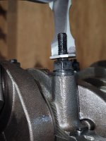
There was also the baffle thing in the pan hitting the pickup tube, but this one was easy enough to work past with some tin snips. It was after this that I found the pickup was bottoming.
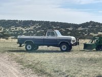
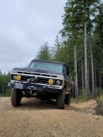
Oh, and went out to a 4x4 park (sorry I know it's not engine related, but it's project related!)


And also finally found a good deal on a DMC crimper and indexer, so I'm running low on excuses to put off wiring

Couple issues I am having at the moment - in having a hard time finding anyone in my area who is able to make a custom fuel rail from extrusion, I'm wondering if at this point I just need to talk with a dedicated machine shop (not an engine/auto machine shop) since it needs off axis holes for the injectors.
The other thing I'm dealing with right now is the oil pan not fitting with the pickup tube. I've got the pickup support pressed down as far as it will go on the main stud before it changes to the larger thread, but it's still bottoming out in the pan. This looks like it would be an issue regardless of the thick spacer I did for the oil pump, since the support bar is what's driving the issue

There was also the baffle thing in the pan hitting the pickup tube, but this one was easy enough to work past with some tin snips. It was after this that I found the pickup was bottoming.

Oh, and went out to a 4x4 park (sorry I know it's not engine related, but it's project related!)


What about making a drop sump at the pickup area just make sure that there is plenty of space around the pickup and about 3/8'' space between the pickup and new sump bottom. I think that would be better that fixing the pickup.
What about making a drop sump at the pickup area just make sure that there is plenty of space around the pickup and about 3/8'' space between the pickup and new sump bottom. I think that would be better that fixing the pickup.
That could be an solution.
I am curious as to why this is a problem, and if anyone else has run into this. Are there maybe 2 different rear sump oil pans with slightly different geometry? The one I have for this motor has the drain plug pointing to the rear, while the one on the 80's era 300 in my truck now has it pointing to the passenger side
I'm trying to get a turbo sorted out and on order because I'm seeing a lot have a 4 week lead time, so might as well get it going.
This is almost my weakest subject and I've not been looking forward to the search... From what I've gathered in wanting to look in the 54-59mm range for what I'm after which is strong midrange power (I think). And when given a choice on a/r, I'm looking towards the smaller end again for quicker response times.
I've (hopefully) attached a comparison sheet I made with info pulled from Summit on a handful of STS and Precision Entry-Level turbos (by no means exhaustive, but I need to start somewhere to pare down my search). From what I understand, STS started out the game with rear mount kits, but I figure a turbo is a turbo and it would be fine in the engine bay.
From the list, the 30502004069 and the STS203 feel like the small side of things with the small compressors and low a/r. Conversely, the 30802008109 and the STS201 are on the big end.
The sts202 and 205 have V band outlets on the turbine which is something I was after, but having a 4 or 5 bolt isn't a deal breaker either because adapters are available to convert it to v band. My initial shot in the dark is either the STS205 with the larger compressor and v band outlet, or the 30502004089 with the smaller compressor.
Any help is greatly appreciated!
Attachments
You are looking for a T4 turbine inlet flange.
The compressor outlet should be a 3.00" V band.
The turbine housing A/R should be between .63 to .68.
The best one for the job is the Borg Warner S257SX-E with the T4 .68 A/R Open 3.00" V Band Outlet
The compressor outlet should be a 3.00" V band.
The turbine housing A/R should be between .63 to .68.
The best one for the job is the Borg Warner S257SX-E with the T4 .68 A/R Open 3.00" V Band Outlet
Last edited:
You are looking for a T4 turbine inlet flange.
The compressor outlet should be a 3.00" V band.
The turbine housing A/R should be between .63 to .68.
The best one for the job is the Borg Warner S257SX-E with the T4 .68 A/R Open 3.00" V Band Outlet
Just to clarify, you mention compressor outlet should be 3" V band, but looking at that Borg Warner p/n everything I see says it's a 2" outlet on the compressor. Is that still fine, or too small?
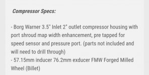
The 3.00" outlet is on the turbine housing.Just to clarify, you mention compressor outlet should be 3" V band, but looking at that Borg Warner p/n everything I see says it's a 2" outlet on the compressor. Is that still fine, or too small?
When I posted "The best one for the job is the Borg Warner S257SX-E with the T4 .68 A/R Open 3.00" V Band Outlet", the "Borg Warner S257SX-E" denotes the core which includes the compressor.
Everything afterwards refers to the turbine housing which is the part you have to select.
I should have been more helpful and made reference to the turbine housing specs by just adding "Turbine Housing" at the end.
Sorry about that.
Last edited:
Got this lovely piece in the mail today 
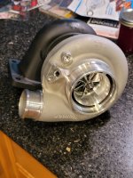
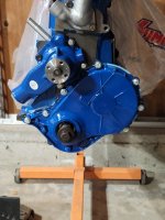
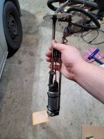
Not too many other things going on the past month. Been recovering from hand surgery (kitchen knives are sharp, lol) and so haven't been able to do much. But I did finally get around to cleaning up and painting the timing cover, and got the fuel pump assembly put together for the tank.
I'm now almost back to full use of my left hand, so I'm going to try and get a couple more things going now, like getting the tank and fill tubes mounted and going back to wiring

Not too many other things going on the past month. Been recovering from hand surgery (kitchen knives are sharp, lol) and so haven't been able to do much. But I did finally get around to cleaning up and painting the timing cover, and got the fuel pump assembly put together for the tank.


I'm now almost back to full use of my left hand, so I'm going to try and get a couple more things going now, like getting the tank and fill tubes mounted and going back to wiring
Lost mine at some point during the disassembly phase and while movingWhere is the timing tab that bolts to the passenger side of the timing cover?
Wasn't planning on changing themLooking good besides the bolts/washers. I assume they are temporary.
I haven't picked a wastegate out yet, thats one thing I really need to do research on because I'm not very well versed in how to pick one (or if there's even much science behind it). As for a blow off valve, I assume I'll need one, but again I haven't looked into itI’m curious if you have selected a wastegate and if you’re going to use a blow off valve. My build is very similar to yours. I’m at the point of choosing these and an inter cooler so I can start mocking it all up.
Past 3 months have been stupidly busy so I haven't had a chance to work on this much
One of the little projects I'm working on right now is sketching something up for an upper intake. I've been in the 'toss spaghetti at the wall and see what sticks' stage, and there's a couple things I have questions on;
For starters, is there much more science behind selecting a throttle body other than not making it excessively large and making sure it's not the smallest diameter restriction on the intake system? In my case, the smallest diameter is the 2" outlet from the turbo and I'll have 2.5" in the intercooler, so it stands to reason I'd be looking around the 60-65 mm range for a throttle body. But I could be off base.
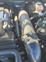
Secondly is more along the lines of intake design theory - My initial idea came from a turbo intake I saw on a 2JZ that wasn't much more than a welded up tube with plates on the ends and runners to the intake flange (first photo below). I started sketching something up that was a similar idea, but instead of having tube runners down, I just have it going straight onto the lower intake. This is based on using a 62mm throttle body, though as I sit here I would probably want 65mm since 62 is smaller than the intercooler piping... but I digress
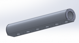
I was trying to think of something that would be easy to fabricate out of simply produced parts, so the manifold flange and TB mount/end cap are just laser cut and welded up to the 4.5" diameter tube.
But back to the more theory question, does TB placement relative to the runners have much of an impact in a turbo build? I.E, is having the air coming in one end of a 28" long manifold going to cause issues with air distribution to the rear cylinders compared to the front? Would there be more benefit to having the throttle body more centrally located on the intake tube?
For starters, is there much more science behind selecting a throttle body other than not making it excessively large and making sure it's not the smallest diameter restriction on the intake system? In my case, the smallest diameter is the 2" outlet from the turbo and I'll have 2.5" in the intercooler, so it stands to reason I'd be looking around the 60-65 mm range for a throttle body. But I could be off base.
Secondly is more along the lines of intake design theory - My initial idea came from a turbo intake I saw on a 2JZ that wasn't much more than a welded up tube with plates on the ends and runners to the intake flange (first photo below). I started sketching something up that was a similar idea, but instead of having tube runners down, I just have it going straight onto the lower intake. This is based on using a 62mm throttle body, though as I sit here I would probably want 65mm since 62 is smaller than the intercooler piping... but I digress


I was trying to think of something that would be easy to fabricate out of simply produced parts, so the manifold flange and TB mount/end cap are just laser cut and welded up to the 4.5" diameter tube.
But back to the more theory question, does TB placement relative to the runners have much of an impact in a turbo build? I.E, is having the air coming in one end of a 28" long manifold going to cause issues with air distribution to the rear cylinders compared to the front? Would there be more benefit to having the throttle body more centrally located on the intake tube?
Throttle body location will affect the plenum volume and the flow of each individual runner. It can get complicated but the design you are considering should be relatively easy to get good results. The reason I say that is the air has to make the exact same 90 degree turn into all runners.
With this design I’d suggest paying attention to the distance from the throttle body to the first runner. If it’s too close it may not flow the same as the others runners. So if there is a 2” distance between runner entries, allow 2” of plenum to extend past the first runner to the flange of the throttle body.
With this design I’d suggest paying attention to the distance from the throttle body to the first runner. If it’s too close it may not flow the same as the others runners. So if there is a 2” distance between runner entries, allow 2” of plenum to extend past the first runner to the flange of the throttle body.
Similar threads
- Replies
- 156
- Views
- 4K
- Replies
- 15
- Views
- 1K
- Replies
- 17
- Views
- 1K
- Replies
- 30
- Views
- 4K
- Replies
- 16
- Views
- 4K

