'76 F250 Turbo Build

We had an intake like this on a 4.2L GM Atlas naturally aspirated for Bonneville racing. Air flow was not equal cylinder to cylinder resulting in varying AFR readings cyl by cyl. We had 6 O2 sensors and sequential injector control with Megasquirt 3. We then had a GM engineer offer to do computer flow analysis and make recommendations. He had us turn the TB 90 degrees with the blade opening clockwise viewed from above and we made a wedge spacer plate to angle the TB towards #1 cyl. This helped but did not fully cure the issue. I would lean more to the original Ford top manifold with the divided plenum. They made it that way for a reason.
As for TB size, I wouldn't go any or much bigger than stock as the turbo will push more air through anyway. The bigger the throttle body the less sensitive it is to low opening for normal driving and the less sensitive the TPS.

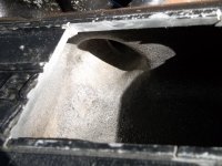
Bonneville car with 4.2L Atlas 6
 
Last edited:
I wouldn’t think rotating the throttle body 90 degrees would be the solution but obviously you proved it to be true. Thanks for sharing.

I have flow tested the EFI intake. The first runner flows 10cfm less than 2-6. The two areas that need attention are the turn into the plenum and at the jog by the sensor.
 
Not recommending anything, but FWIW the upper EFI intake is extremely beefy. I cut one open and there's plenty of meat there for air compression. Distribution would be unbeatable, but @ aprox. 300 cu in of plenum volume, spool-up and throttle response would be slow. Once it was wound up though, look out. . I've yet to see any intake better suited for the 300 than the factory EFI. I believe this would be true under boost too, but street 4 wheelers want quick response. I've driven trucks which took 2-3 seconds to spool. But once the 3 seconds of jet-black smoke cleared, everyone was looking at my taillights.
 

Attachments

  • 100_0433.JPG
    100_0433.JPG
    2.8 MB · Views: 14
The log type plenum with the TB on the front will still be 300 cu in and could be an issue with awkward air plumbing from the intercooler if the intercooler exit is on the driver's side. Whereas the stock TB location allows simple plumbing routing. Longer air plumbing will also have some adverse effect on throttle response time. A Clifford or Aussie Speed intake that will accept injectors might be the best option for good air distribution and smaller plenum. If using the stock EFI top half intake, note that the newer version ('95+ MAF version) have a design change that might be favorable.

1NXX46u.jpg


QtCHyM0.jpg
 
Last edited:
Air side plumbing is less of a concern since I'm planning to use a small air/water Intercooler and I'd like to have it also on the drivers side to keep piping as short as I can.

I'm not familiar enough with the upper efi intakes, but from what I recall they hug the valve cover pretty close so might not clear the tall Aussiespeed finned cover I have, but I may be mistaken.

I went with the 4.5" since that made for a simple TB plate when I was throwing that together but I can likely make it smaller. I'm also not beholden to a tube based log. I can make up a bent sheet metal box style with the TB top or front mounted
 
I'm not familiar enough with the upper efi intakes, but from what I recall they hug the valve cover pretty close so might not clear the tall Aussiespeed finned cover I have, but I may be mistaken.
Correct. In stock configuration it will not clear the VC.
 
Air side plumbing is less of a concern since I'm planning to use a small air/water Intercooler and I'd like to have it also on the drivers side to keep piping as short as I can.

I'm not familiar enough with the upper efi intakes, but from what I recall they hug the valve cover pretty close so might not clear the tall Aussiespeed finned cover I have, but I may be mistaken.

I went with the 4.5" since that made for a simple TB plate when I was throwing that together but I can likely make it smaller. I'm also not beholden to a tube based log. I can make up a bent sheet metal box style with the TB top or front mounted
I like the Water/air cooler for keeping the plumbing short. And the formed box section plenum with the TB central and the plenum tapered toward the ends to control the volume. The TB could be on the side of the plenum for hood clearance.
 
Well, I finally have something new to update! I have my fuel rail all sorted out now. I ended up sending my intake and injectors off to Induction Solutions in Florida and they were able to make up a rail and mounts. Now, they usually work on drag cars so their small size fuel rail has -8 ends and is -10 in the middle, and supports up to 800 HP per rail, so it should work at my power level lol. All in all they were great to work with, and this was a well spent $300 in my mind. About a month between when I shipped it to them and when I got it back, but that was also with shipping ground from WA to FL

20230221_160343.jpg

20230221_160351.jpg

20230221_160421.jpg
 
Well, I finally have something new to update! I have my fuel rail all sorted out now. I ended up sending my intake and injectors off to Induction Solutions in Florida and they were able to make up a rail and mounts. Now, they usually work on drag cars so their small size fuel rail has -8 ends and is -10 in the middle, and supports up to 800 HP per rail, so it should work at my power level lol. All in all they were great to work with, and this was a well spent $300 in my mind. About a month between when I shipped it to them and when I got it back, but that was also with shipping ground from WA to FL

View attachment 15090

View attachment 15091

View attachment 15092
That's honestly less than I expected for a custom rail and mounting like that. 👍
 
That's honestly less than I expected for a custom rail and mounting like that. 👍
Same, which is why I was stoked when I found their deal. Shipping to and from added another $120 total since its big and I'm far away, so real cost is really $420, but I'm still happy with it.
 
Looks nice! Was the factory rail just to small?
Also what injectors are you using?
Thanks! The injectors are Accel brand 44 lb/hr, and if I remember correctly the stock injectors are around 18-22 lb/hr, so with doubling the Injector flow we were worried the factory wouldn't flow enough.
 
Last edited:
Worked on a solution for the oil pump pickup issue. I didn't want to try having the sump dropped on the pan itself since I'd have to pay someone else for that, so I went about modifying the support to adjust the height of the pickup.

20230305_185430.jpg

20230305_185353.jpg

20230309_180259.jpg

20230309_180717.jpg

--
I've also spent a little more time over the past couple weeks spitballing how to mount the IGN1A coils. My original plan when I started buying parts was to have an inspection cover made with mounts to put the coils down low. But taking into consideration the distributor body that may be there and wiring concerns, I'm thinking inspection cover might not be the best idea - even looking at different mount orientations. Not to mention most ideas blocked the bolts so the coils would have to come off to remove the inspection panel which is not ideal.

So I started looking at that nice, smooth expanse of cast aluminun valve cover and thought I might be able to make something there work. My first thought was making a bent steel bracket that uses some of the valve cover bolts and other threaded bosses on the side of the head to mount to, but then it occurred to me why not weld threaded inserts directly to the side of the cover? It's thick enough aluminum to do so, and with proper jigging and heat management it shouldn't warp the cover... Just sucks that I bought the one already powder coated instead of the raw finish one. I might end up buying the raw finish cover and see about selling this gently used cover.

20230309_182544.jpg
 
Went to mock up the manifolds today now that I have studs in, and ran into a couple problems. First off, the last exhaust bolt hole to the rear of the #6 valve is cast, drilled, and tapped way off from where the HD manifold has a full tab for it, so I'm not going to be able to run the last bolt on this manifold. Is this a big deal, given that it's the only full bolt tab other than the oversized one in the front? Without much else to compare too I can't tell if this is an error in the head casting or manifold casting

20230312_150621.jpg

Next thing I found while mocking up the intake is that the forward-most hole directly above #1 was never finished by Promaxx. It's only drilled down 0.66" compared to 0.98" on the others, and isn't tapped. I can tap this hole so I can at least get a stud in there, but I don't know if I can drill it deeper without running into something - or if it even needs to be finished out to ~1" deep like the others
20230312_150909.jpg
 
Solved the mystery of the untapped hole - it's for a dowel. Never noticed that before so I'll chock that up to a dumb brain moment
 
Back
Top