'76 F250 Turbo Build

I've got pedestal mounted rockers, so no lashing on these. That's not a bad idea, I don't live where it's super humid all the time but so far I haven't seen any signs of issues inside the cylinders. I do rotate the motor every now and then to make sure nothing gets sticky.
low humidity and periodic rotating- (y)

It was so bad here in late December when I got the raw block back from the machine shop: A cold front from the NW dropped temps, then a wave of pure tropical ocean air would roll in 'couple of days later. Anything metal literally dripped water, was totally wet all over, the cold iron condensing the air moisture. . The whole rebuild process took several months, but I had the engine buttoned up in a few days. . Good thing we had no company or plans at Christmas, that's what I was doing, beating the rust.
 
God, been a minute hasn't it 😅 life has a habit of getting in the way of things.

At any rate, haven't done much over the past couple months. I have finally gotten the tank mounted, which as I had mentioned before was a pain. Still very disappointed by the product for a number of reasons.

Notched the bed support to clear the EFI module
20241116_164057.jpg

When it was all said and done, I still had to use 1" spacers on the front tabs.
20250105_175814.jpg

I will probably replace these with blocks at some point to reduce the risk of cracking the tabs around the bolts.
20250105_180042.jpg

And though all this I found out that this tank "made for highboys" also
1. Has the vent and fill tubes opposite a factory filler neck orientation (fill neck head the vent on the rear, tank has it on the frontside)
2. Has a 2" filler neck and 1/2" vent barb compared to a 2.5" and 3/4 combo on the filler neck, so I'll have to adapt down a factory fill hose, somehow

Really really disappointed with the whole experience, but at least it's in. Going to be ordering up some nicopp soon to make my hard fuel lines, and run a wire for the pump back up front
 
Spent the past 2 weekends running the hard lines to the front of the truck. Used 3/8 for the supply and 5/16 for the return, both lines Nicopp. The smaller one went in pretty easily and I was able to bend it by hand with sockets for the radius with no problems. The 3/8" however was a royal pain and kinked on me twice, at both ends. The one at the back isn't super bad, so I'm debating running it. That end is flared for the rubber hose so I can't really cut and flare in place, and I don't know if I'll be able to fish the whole 12' line out again.

At the front I was able to just cut the kink off and my flex line connection will now be down in the frame instead of close to the top like the 5/16. For consistency sake I may also take the return line back down inside the frame so they match. And now that I think about it, I'll be able to stab a fuel filter in right where the hard line ends.

Overall didn't go as poorly as I feared, I've never really run hard lines like this before but the nicopp made it pretty easy.
20250222_173726.jpg

20250222_173743.jpg

20250222_173836.jpg

20250222_173849.jpg

20250222_173935.jpg

Also mounted up the fuel pressure regulator. I didn't really want to put more holes in the firewall if I didn't need to, so it went on the fender. It's going to be a bit hard to adjust when the hood is on, but in theory won't need to be getting back there much.

20250216_185522.jpg
 
Nice work. The regulator is not hard to get to there. I have them there in 2 trucks. I'd suggest setting them so the gauge can be seen from above, that's going to be your difficulty when tuning. Either reorient the regulator or add a 90* elbow so the gauge can be seen directly.
 

Attachments

  • DSC06604.JPG
    DSC06604.JPG
    2.2 MB · Views: 9
Nice, high pressure and a low pressure gauge. I hadn’t thought about that🥹, good idea👍
Not to sidetrack jgavac's thread- that regulator is the secondary regulator in this rig: Factory in-tank EFI pumps to hi press return regulator on the frame. 70psi down to 10 or so, high volume returns to tank. Then to this non-return carb regulator to get the slightly irregular 10 psi pressure down to a stable 5psi, into the carburetor. Perhaps not ideal, but has worked effectively for 10 years. Each gauge monitors one regulator.
 
Another side project I've been working on for a while is a mount for the coil packs near the spark plugs. My original thought way back when was a custom inspection cover with screw bosses machined in and running the coils "flat" against the inspection cover, but the price of material alone made that a nonstarter, not even considering machining costs. Then I thought, what about welding bosses to the (aussiespeed cast aluminum) inspection cover or valve cover, which could work, but I'm not a welder so again a bit of a non starter. Plus, I already had the valve cover in wrinkle black, and didn't want to grind it off.

So I thought, you know what is cheap and easy is bent sheet metal parts, and I still have the inspection cover bolt holes to work with. And here we are - The inspection cover is symmetric around the middle, so whatever worked for the front stack should also work for the rear stack. This meant just 2 unique brackets, with similar designs, but the rearward one being a bit longer. Spacers are 3/4" at each end and 1.5" in the middle, and the whole thing goes together with 2 pieces of 1/4" all thread rod.

Messenger_creation_FAEF0EE5-F2BC-45BC-801C-77DAD9686CF4.jpeg

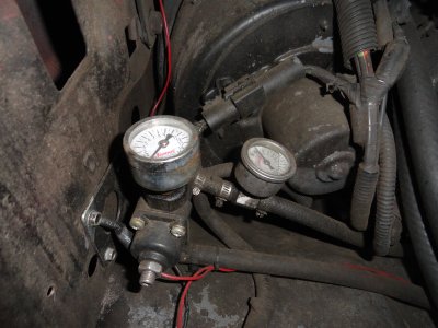
Shoot off the brackets to sendcutsend, and a donation to McMaster Carr for the spacers and rod, and a week later I was able to test fit.
20250328_165621.jpg

Add in the matching aussiespeed side plate (after 3 years lol), and here we are.
20250331_210901.jpg

20250331_211122.jpg

Truthfully, the vertical offset was a bit arbitrary. When designing in Solidworks I assumed the inspection cover was completely vertical, so I offset up to make sure there would be room to the injector harness underneath, but it ended up being less of a problem than I thought because the cover angles inwards a bit, splaying the plugs out. And I biased the packs toward the front (at least, in the front stack) to make sure there'd be enough room for the distributor.

At any rate, I'm pretty happy with how these have turned out. Didn't look 100% like I imagined (sticks out more than I thought it would), but it keeps the plug wires short and the coils tidy.
 
Slowly but surely marching forward. As I may have mentioned before, I didn't like how the bulkhead plug was going to mount, and it would trap the interior harness. No Bueno. So, I wanted to have a hole large enough to pull the plug through, but meant I needed a plate to mount the plug to.

Also, how the heck do you enlarge an existing hole with a hole saw when you don't have a pilot hole? I went for a drill guide. Had this cut out of abs to first drill the 4 bolt pattern, then use those bolt holes to hold the guide while I enlarged the hole.

20250511_140305.jpg

20250511_144235.jpg

20250511_144442.jpg

After this, I was finally ready to pin out the bulkhead plug. Lopped a couple of feet off the cab pigtails, and went to work.

20250516_191323.jpg

After running a continuity check across the whole assembly (no issues!), I taped and wrapped the interior harness, and test mounted the whole assembly.

20250524_182636.jpg

20250524_182922.jpg

20250524_182943.jpg

20250524_183119.jpg

This is far from perfect. The extra length I left in the cab is a bit hard to find a home for, I got the wrong size braided loom for the main harness so sometimes a wire will pop out, and my heat shrink boot didn't go well, but I'm not complaining too much for my first time ever doing this!
 
I see you got it figured out. I have an attachment for a hand drill similar to the photo. The drill mounts in the small hole, the base rests on the project, the drill can then slide down the guides an drill the hole without a guide
 

Attachments

  • IMG_4440.jpeg
    IMG_4440.jpeg
    116.7 KB · Views: 3
Back
Top