Crankcase ventilation solutions?

George66Falcon

Active member
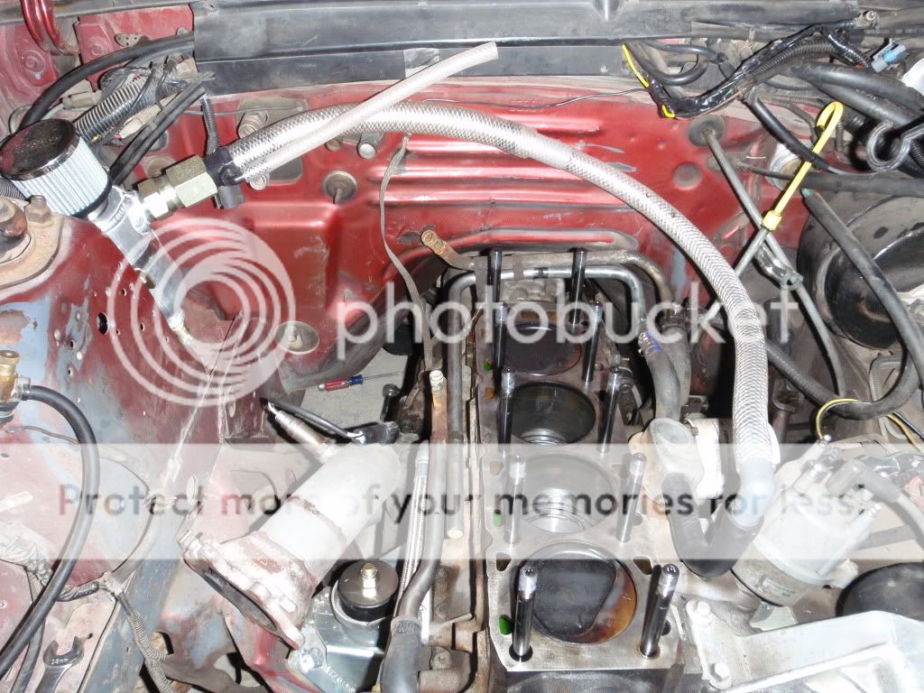
Hi there, folks! I have a 200 with the 250 2v head and m62 supercharger. I'm getting an oily mess over everything, and I'd like that to stop!! What solutions have you folks used to keep the oil and oily air in/off the motor? Thanks in advance, I look forward to hearing what you've got to say.
 
I get some oil vapor escaping under boost with a 250 w/supercharger. Currently has two open breathers but I'm going to add a Catch-Can since the boost vapor is supposed to be especially nasty and better removed than returned. A turbo specific PCV valve can be used or open breathers. Looking to figure out where it needs to mount referenced to the VC or PCV ?.

OF course this is dependent on the engine is in reasonably good shape, meaning the blowby only serious while under boost, if the engine has blowby from guides or rings while NA, nothing will help the oil smog when under boost. The 250 had a turbo previously which ended in oily smog plume when the piston lands broke off...

... blowby can be routed back into engine with a turbo specific PCV to intake or even siphoned into exhaust :
http://www.superchargerforums.com/threa ... lown.2472/

have fun

/
 
Away from the forum, but still luv a good read....Back to my auditing missing signs and potholes......

NZ_STOCKpLUMMETS.jpg


m16_night_drive_over.jpg


Oh yeah,

#9 by xctasy » Thu Jun 30, 2016 has the total turbo charged Fox 2300 Lima set up that uses the stock PCV oil seperator, a Catch Can, and some added length of hoses to ensure no drain back oil windage issues. This lookes after blow by in the best possiable way.

The same EAO2.0 /Lima 2.0/2.3 catch can uses a two way system like the Capri RS Turbo, Mustang GT turbo, Mustang SVO and Merkur XR4Ti and Thunderbird Turbo SportsCoupe used from 1983 to 1988. Here is a common after market modification with an extra external catch can and blow by protection.

SVONewSetup14.jpg


Turbo charged Ford guys are totally the knowledge base you need to follow.


http://vb.foureyedpride.com/showthread.php?178151-adjusted-idle-hooked-up-pcv-cam-lope-disappeared

Postive Crank case ventilation totally influneces idle on carb vehicles,

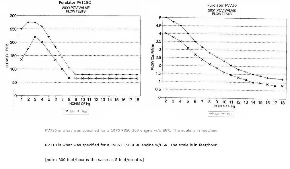
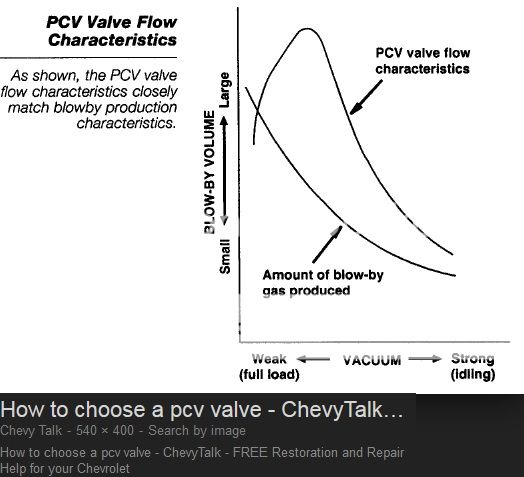
Fords Holley Weber carbs had to be protected by specially calibrated EGR sensitive PCV valves, the demand cycle traded off against the blowby figures. On big sixes of 300 cubic inches, one valve services a 5 cfm peak blowby from all six cylinders. If its has no EGR and a 1-bbl, its one type of really simple valve. If its EGR, they have a balanced type.


On a 5 liter V8, its about the same.

5CFM_BLOW%20BY%20SCALE%20FOR%20PCV_VALVES_20F2.jpg


5CFM_BLOW%20BY%20SCALE%20FOR%20PCV_VALVES.jpg


https://youtu.be/nd92jPRH3YY?t=123

Wagner_Adjustable_PCV_valve.jpg


The right PCV can allow a much more sensitive air blead calibrated carb to operate. Often, just baffels below the PCV are enough, but the Wagner Adjustable PCV avoids high blow by charge dillution, which is another huge issue on why the air bleeds clogg up. Basically Ford of Europe sorted the idling issue out with bleed back fuel lines, and balanced PCV with an air baffle to stop oil consumption from blow by.

Baffle1-results-R1.jpg


https://fordsix.com/viewtopic.php?f=1&t=73925&p=574647#p574647

"Engine will not idle - Weber Carb Tunning problem"

Small Ford Six cylinder cars with 90 degree bend cast iron itake manifolds and a 2-bbl Weber carb hop up are the worst idling cars around, and they get fixed when using a balanced PCV like Fords Lima/Pinto OHC item, which is exactly what the modern Wagner Adjustable PCV does.


Everyone puts an unbaffled crome rocker cover on em, and they suddenly cant make em idle, and they foul up plugs and run log dawgs...


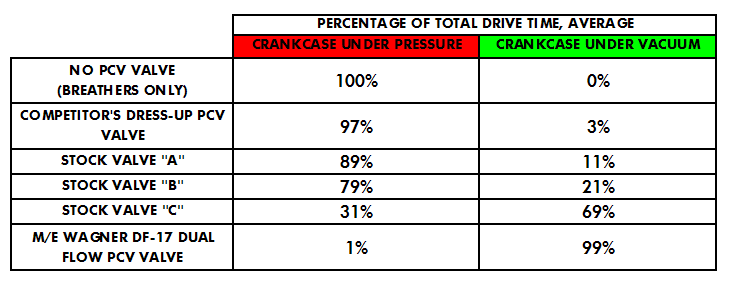
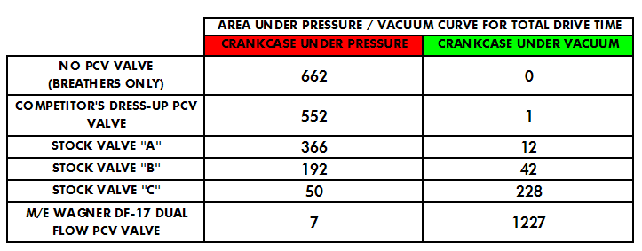
Table 1 and 2 are pure advertorial, but the basic idea is what Ford were doing in 1969 with the two lit(re) Pintos....cutting off blow by and using the PCV to create a two stage vaccum. It wasn't Wagner who invented the idea!.

Flow-results-percent.png


Flow-results-integral.png
[/QUOTE][/QUOTE]


"Air Fuel Ratio - Page 3 - Four Eyed Forums - FourEyedPride.com"

xctasy":1t5m441e said:
Cool.

Just a note. The removal of blow by is based on the dyamic leak down rate of 3 cfm at 5000 rpm overall for a Formula 5000 or TransAm or AVESCO 630 hp 302 SB Ford or Chevy making 450 lb-ft of torque at 5000rpm. Thats 3/8ths of a cfm per piston for an engine making about 630 hp at 7500 rpm.

David Vizard allowed for a heck of a lot more blowby than most Americans would be confortable with. The 1275 would have to have a 37% leakdown rate to pass 18 cfm of blow by, but that is how the evacusump system is oversupplied by the suction force of the exhaust, and that gives depressions of 1.85 to 2.60, and the vaccum really unloads the rings to reduce flutter.

Or your engine making, say, 135 hp stock with cam, then maybee 215 hp turboed, then perhaps 315hp with a turbo and nitrous. Blowby is proportiona to torque gain under nitrous as well, so it will go up 50% with nitrous, balooning the normal wear environment on the piston, and pehaps making 2.25 cfm total in good shape, 9/16ths of a cfm per piston. As the rings and bore wear, blowby will go up as the static leakdown rates (measured under a 24 hour or overnight test pressure) drop from 80 to perhaps 65% for an engine getting really tired.


I'd expect a static leakdown of 80% to yeild those kind of 2cfm figures at about 4000 to 5000 rpm under the giggle gas. . Engine health is best measured by blow by pressure if Evacusump, as the rings are unloaded by the system. The life remining can be drastically increased by having a little think, and then deciding to incorporate some kind of Evacusump stratergy.

Like everything, its your car, and you don't have to incorporate a xctasy grocery list of wack job ideas...but it sure as heck is an awesome indicator of engine health, a barometer which if used, will allow you to confidently lean a little harder on your 2.3.


See http://performancetrends.com/Blowby_CFM_Flow_Sensor_Meter.htm#Typical-Blowby-CFM-Table


Lastly, blow by on these poorly oil return drain back engines defines remaining engine life...

xctasy":1t5m441e said:
Go to a library, and get this book if you can.

51AT0ZZDH7L._SX354_BO1,204,203,200_.jpg


http://www.amazon.co.uk/Tuning-British-Leylands-Series-Engine/dp/0854297324


Tuning British Leyland's 'A' Series Engine Hardcover – Aug 1989

The problem with your high rpm air fuel ratio swing is blow by.


The way to fix it is to remove it by an evacusump system, two 5/8" PCV valves to the intake manifold from the rocker cover.


And then two anti back fire valves flowing in excess of 18 cfm each from the lower turbo manifold flange to a dedicated rocker cover catch can.

David Vizard described on in pages 398 and 399 of his second edition of modifying BMCs A series engine, and discussed Turbo applications specfically. Diagrams 15.2a, and 15.2 nail the sysyem down.


Its also covered in


images


How-to-Modify-Ford-s-o-h-c-Engines-David-Vizard

http://www.scribd.com/doc/26804743/How-to-Modify-Ford-s-o-h-c-Engines-David-Vizard#scribd


page 79 -85 Chapter 5 "Exhaust Manifold & Exhaust System"


and page 115

"This practice is relatively new and, as far as I know, it originated in the U.S.A.

A Pressure-balanced lubrication system is a means of reducing the air pressure in the crankcase so the rings and valve seals have fewer tendencies to pass oil up into the combustion chambers. With air pressure reduced in the crankcase, the reverse tends to happen.

The higher pressure gases in the ports and combustion chambers tend to come down by the rings or seals and end up in the crankcase. Now at first this may seem to be the wrong way of doing things but it does have several advantages......"


"......This brings us to crankcase ventilation. On very high-rpm turbocharged engines, ventilation of the crankcase becomes super-important. Unless there is space for plenty of air to move in and out of the crankcase, the engine is likely to blow an oil mist out, covering the engine’ compartment with oil. It will also drop oil on the track and your fellow competitors will not thank you for this"


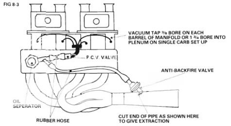
Fig_8_3_dv_sohc_pinto.jpg


Fig 8_3, page 115 with just one 18 cfm PCV.


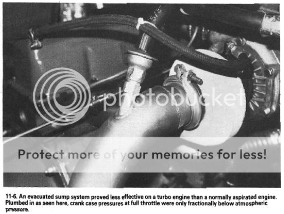
In the A series 2ND Edition book, DV said that blow by from valves and pistons collectively defines remaining engine life. An Evacusump system should pull 1.85 to 2.65 inches of Hg suction at operating temperature. When the figure drops below that, it only has 15 to 30 minutes more operation time at full load.


Fig from Page 135

Page%20135_dv_sohc_pinto_turbo_Evacusump.jpg
 
George, what needs to happen is you need to ventilate the crankcase from the crankcase ,like it was originally designed and not only the valve cover. What happens with a boosted or high rpm engine ,the extra blowby blows up the lifter drain back holes and up the push rod holes prevents oil from rockers form draining back, this also will eventually empty the sump, effecting oil pressure. The valve cover will be more than flooded with oil, easy for oil to breath out the cover.

Remove fuel pump, make a tall larger baffled vent to help vent the crankcase at the crankcase. All venting must be baffled well.
Search U tube "south american falcon drag cars". You should find some pics of this.
 
Strong advice - good PCV is critical on boosted cars, open-air breathers just don't provide the same function. Modifying the fuel pump hole for direct crankcase ventilation is a good plan. You could use a separator from production turbo car here, or make something yourself.

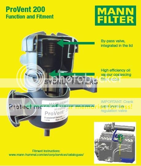
I recently learned about the Mann Pro-Vent, which has been retrofitted to a bunch of turbodiesels to assist with PCV functions. I just got a 200 model for my diesel Jeep with the intent on evaluating it for use in the XR4Ti, but it's GIGANTIC. Might fit in with an inline six, though! :) There are smaller 100 and 150 models, but the 200 is easier to find and has simple hose barbs to attach to the engine which makes installation easier. I'm trying to find a source for the smaller 150s so I can make a fitting - I think it's better suited to normal passenger vehicles. The 200 is clearly designed for bigger trucks. :) Still worth considering though - it's exactly the right idea for top-notch PCV in a boosted environment.

 
On my old motor which had blow by like crazy I ran two catch cans. One had a hose from the front breather cap to the can, then ran a hose from the can to the front of the turbo. The other ran a hose from a cut open PCV valve (took the stopper out so its essentially just a pipe nipple at this point) to another can and then a hose from the can to a spot under the carb. Worked great for that setup.

I now run a catch can that I made out of a stainless water bottle with an open breather filter for a lid. I will take pics to show later. It runs from the breather lid to the can. I then run a PCV for a late 80's Mustang SVO with a hose to the intake. I will likely add my other catch can in line with this setup one day if I feel the need but for now Im only just getting it running well enough to get it tuned to putt around town.

Matt
 
I liked the idea of using the blocks' Fuel Pump flange for a crankcase vent. I have tapped a hose fitting into the fuel pump block-off plate and plan on running a catch can with breather from there. I would like to retain the valve cover PCV setup to intake for some vapor recovery. Maybe valve the crankcase vent can open under boost, maybe with exhaust siphon.

haev fun
 
powerband":3uwjwfnn said:
I liked the idea of using the blocks' Fuel Pump flange for a crankcase vent. I have tapped a hose fitting into the fuel pump block-off plate and plan on running a catch can with breather from there. I would like to retain the valve cover PCV setup to intake for some vapor recovery. Maybe valve the crankcase vent can open under boost, maybe with exhaust siphon.

haev fun

My new build plan is...What I have seen on you tube is they fab the largest area tube to the opening,they probably port the block also..The idea is to slow down the blowby with area so oil does not get blown up and can drain back.
The exhaust siphon does not work well with a muffler and long exhaust pipe..My down pipe was 3" 24" long, Because of the oil drain back issue I almost crashed ,sucked over a quart of oil out of valve cover and blew it under the tires. :oops: Changing to side exit exhaust and crankcase venting with separator and suck from there. I think the sucking should be from the crankcase to promote down flow of the oil in the valve area ,maybe a vent in the cover would be ok?
 
If I can find it I will post it, but I read some information about PCV design, and the forces in play that you have to deal with. You need the suction point to be sufficiently higher than the vent so that you're only sucking air and not oil, but you need to keep it short enough that the contents don't cool down and coagulate, and you need adequate baffling so that air goes back into the intake but not oil.

The problem with exhaust drafts is that the suction is coming from below the engine, and that creates the ready potential to start siphoning oil out of the sump. A air:eek:il separator placed at the top of the engine bay is going to offer the best performance. The suction point wants to be a place of high vacuum, which on a forced induction car is going to be pre-blower/turbo. You need a good way to clean the PCV air so that you're not blasting the blower/turbo with dirty oil. A traditional catch can will address that, but on a car with high blowby you can overwhelm the catch can - a friend of mine used to fill his on a boosted 300ZX after ever autocross run. The advantage of that Mann Provent is the replaceable filter does a better job that any baffling, so you can return the separated oil to the sump. It's really a good design.

On an OHV engine I'm not sure you really need to suck from the head like you would an engine with a timing belt. You are addressing blowby, and assuming you have good suction on the crankcase there won't be any gains from a second top port. I think a better approach would be a filtered vent on the valve cover so PCV on the crankcase can draw fresh air through the valve cover, down the oil drain holes, and out the block. Pipe that into a good catch can or the Provent, then into the intake. My 8v Saab and my Ford 2.3t both draw PCV across the air filter to ensure any particles still hanging in the air don't get back into the engine and that seems like a good idea. My Volvo and 16v Saab both dump the PCV right before the turbo, which seems like a less good idea. ;)
 
thesameguy":3rlmvow7 said:
If I can find it I will post it, but I read some information about PCV design, and the forces in play that you have to deal with. You need the suction point to be sufficiently higher than the vent so that you're only sucking air and not oil, but you need to keep it short enough that the contents don't cool down and coagulate, and you need adequate baffling so that air goes back into the intake but not oil.

The problem with exhaust drafts is that the suction is coming from below the engine, and that creates the ready potential to start siphoning oil out of the sump. A air:eek:il separator placed at the top of the engine bay is going to offer the best performance. The suction point wants to be a place of high vacuum, which on a forced induction car is going to be pre-blower/turbo. You need a good way to clean the PCV air so that you're not blasting the blower/turbo with dirty oil. A traditional catch can will address that, but on a car with high blowby you can overwhelm the catch can - a friend of mine used to fill his on a boosted 300ZX after ever autocross run. The advantage of that Mann Provent is the replaceable filter does a better job that any baffling, so you can return the separated oil to the sump. It's really a good design.

On an OHV engine I'm not sure you really need to suck from the head like you would an engine with a timing belt. You are addressing blowby, and assuming you have good suction on the crankcase there won't be any gains from a second top port. I think a better approach would be a filtered vent on the valve cover so PCV on the crankcase can draw fresh air through the valve cover, down the oil drain holes, and out the block. Pipe that into a good catch can or the Provent, then into the intake. My 8v Saab and my Ford 2.3t both draw PCV across the air filter to ensure any particles still hanging in the air don't get back into the engine and that seems like a good idea. My Volvo and 16v Saab both dump the PCV right before the turbo, which seems like a less good idea. ;)

Your last paragraph is what I was trying to say, I was trying to say do not just hook up a small hose to the fuel pump block off plate to go to the catch can separator... Make Like a baffled riser that goes up high as you can then to separator. Boy do I hate trying explain my self in text I need a talk to type app.
 
Just following along on this discussion.
Why not use the old "Road Draft Tube" mounting location to add some kind of scavenging pump ?
I just pulled the "not a freeze out" plug out of my C6 200 block ( very front drivers side corner of the engine block) and the block casting is still open to accept the road draft tube ,even has the 2 mounting bolt holes . It opens into a passageway above the crankshaft.
I can't vouch for the newer blocks, all mine are C6 through C8...
For people still running a mechanical pump, this might be a good place to tap into all the blowby ?
DannyG
 
Danny,
The road draft location is a great place to vent the crank, that is where ford designed it to vent that is why we get into trouble with valve cover venting. The reason I like the fuel pump location is 10x the blocks that do not have it, none of the 250s have it and you would not have to redo if a block changed happened...Your C8 block has it?..The one I have does not.
 
My C8 block is at the machinist so I can't compare it right away.
Next time I stop by I will doublecheck that.
DannyG
 
Back
Top