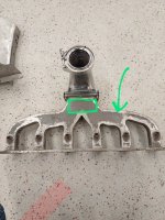
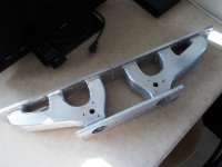
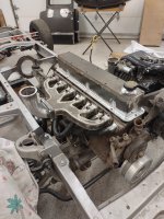
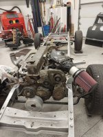
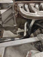
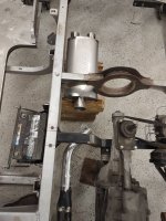
That is correct. In some OE cases there is a solenoid connected to the underside that can connect it to the same vacuum manifold location so Engine Management can kill boost like between shifts or if there is a problem but we don't care about that.In OE use, it looks like the vacuum side of the actuator, is hooked between TB and SC, with no other input?
Between spring tension, preload, arm length/angle, it should allow for a passive off-boost bypass, no?
You are using an out of date browser. It may not display this or other websites correctly.
You should upgrade or use an alternative browser.
You should upgrade or use an alternative browser.
M112 - 300 Build for the '56
- Thread starter clintonvillian
- Start date
clintonvillian
Famous Member
I just noticed there is a port on the bottom side of the throttle body, what is that for?
Does it enter before or after the TB blade?I just noticed there is a port on the bottom side of the throttle body, what is that for?
clintonvillian
Famous Member
It is behind the blade, right in between the two blades. Probably 3/8 in diameter. I'll get a picture of it...Does it enter before or after the TB blade?
The cheap-o wastegates on amazon have pretty decent reviews. Most guys are swapping to TiAL springs, then sealing them back up. Think one would be good enough to get mocked up and off and running... OR should I even bother with one at this point and just see how it does on the dyno...
I need to find some sizes/dimensions on one and I could weld the port in without actually buying one up front. Same goes for the water/meth system.
I would run it on the dyno first and see what the actual boost and power level is.
The water/meth injection should be added before the dyno run so you can see the before and after effects on the dyno.
I don't think you will want to decrease power so save the wastegate installation.
If you decide you need it, removing a pipe and installing it is easy enough.
The water/meth injection should be added before the dyno run so you can see the before and after effects on the dyno.
I don't think you will want to decrease power so save the wastegate installation.
If you decide you need it, removing a pipe and installing it is easy enough.
clintonvillian
Famous Member
Trying to understand the regulator. I found the picture below...You mount the wastegate on the pipe after the supercharger and vent it back to the throttle body.
The bottom port boost reference line also connects to the same pipe.
The wastegate will begin to open as the pressure approaches the spring pressure and will regulate the pressure at that point.
You can use a 3, 5, or 7 lb spring as a base line pressure.
If you add a 0 to 15 psi air pressure regulator and connect it to the top port of the wastegate you can increase the boost above base with a twist of the regulator knob.
The decreased pressure from the wastegate will also decrease the heat so no need to decrease the drive ratio and decrease maximum boost available.
So I disagree with decreasing the supercharger drive ratio when you can simply change the boost pressure with a twist of a knob.
So does the boost reference line put pressure on top of the diaphragm to help increase the pressure needed to open, or does it put pressure on the bottom to assist with opening?
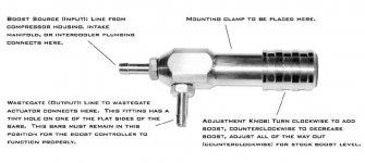
The boost reference line goes to the bottom of the diaphragm so the pressure works against the spring in the top of the diaphragm to open it.
When the boost pressure becomes greater than the spring pressure the wastegate begins to open.
When you add air pressure to the top along with the spring you are increasing the pressure needed to open the wastegate the same as if you added a stiffer spring.
I would use a better 0 to 15 lb regulator that has a place for a guage.
clintonvillian
Famous Member
Thanks,
So if I am using a 5lb spring, and then turn the dial to 0 (completely closed), it will open at 5 psi. If I increase the dial to 10 psi, it will open at 15psi?
Having said that, you could not completely close it, or it wouldn't open at all because there is no place for the air to escape...
So if I am using a 5lb spring, and then turn the dial to 0 (completely closed), it will open at 5 psi. If I increase the dial to 10 psi, it will open at 15psi?
Having said that, you could not completely close it, or it wouldn't open at all because there is no place for the air to escape...
Correct. The air pressure adds to the spring pressure.Thanks,
So if I am using a 5lb spring, and then turn the dial to 0 (completely closed), it will open at 5 psi. If I increase the dial to 10 psi, it will open at 15psi?
Having said that, you could not completely close it, or it wouldn't open at all because there is no place for the air to escape...
A real air regulator will let the air pressure relieve in order maintain the pressure it is set at. The regulator is never off even at 0.
That lets the spring chamber vent to maintain the regulated pressure as the diaphragm moves upward against the spring whether the regulator is set to 0 or some higher pressure.
You are looking at something along these lines for a regulator.
Proximity Miniature Pressure Regulator, MPR1-1, 0 to 15 psi, Air: Amazon.com: Industrial & Scientific
Proximity Miniature Pressure Regulator, MPR1-1, 0 to 15 psi, Air: Amazon.com: Industrial & Scientific
www.amazon.com
Last edited:
clintonvillian
Famous Member
3.5 MAP sensor good?
Where should I locate it and the air temperature sensor at? Closer to the plenum near the intake ports?
Also does it really hurt to just vent the water/methanol to the air? It is basically washer fluid right?
Where should I locate it and the air temperature sensor at? Closer to the plenum near the intake ports?
Also does it really hurt to just vent the water/methanol to the air? It is basically washer fluid right?
Last edited:
Both MAP and air temp sensor should locate in the intake manifold.
They need to see what the intake ports are seeing.
A 3.5 MAP is good for 37 psi.
You get better resolution if the MAP sensor is closer to the maximum boost.
What do you want to limit the boost to?
They need to see what the intake ports are seeing.
A 3.5 MAP is good for 37 psi.
You get better resolution if the MAP sensor is closer to the maximum boost.
What do you want to limit the boost to?
clintonvillian
Famous Member
Do you include atmospheric?
Holley only offers the 1/8 NPT in a 1 bar for NA or the 3.5 bar... The others use the nipple....
 www.holley.com
Which would probably work fine...cheaper too, and can use oem stock units. Just liked the thought of 1/8 npt.
Holley only offers the 1/8 NPT in a 1 bar for NA or the 3.5 bar... The others use the nipple....
Holley EFI 538-13 MAP Sensor
2 Bar MAP sensor is to be used in all forced induction applications up to 14.7 PSI Boost
Which would probably work fine...cheaper too, and can use oem stock units. Just liked the thought of 1/8 npt.
clintonvillian
Famous Member
Oh, you mean run a hose from an 1/8" npt port to the 2 bar map I listed and mount it somewhere else...makes senseA 2 BAR will give the HP much better resolution and tighter control over fuel.
A remote MAP sensor is better isolated from heat and engine vibration
Also will the headers have any affect on the air temp sensor being mounted in such close proximity?
Not directly.Also will the headers have any affect on the air temp sensor being mounted in such close proximity?
The air sensor responds to the air temps that flows by the tip which will be inside the intake manifold.
The headers sit under the intake manifold and will heat the intake manifold unless you do something to prevent the heat transfer.
At least wrap the headers for the sake of the starter and intake manifold.
clintonvillian
Famous Member
I would mount everything on top which would block the heat from the exhaust.
You may need manifold vacuum/pressure for something later. Add two spare.
The air temp sensor uses a 3/8"-18 NPT thread size.
You may want to wait till you get one to finalize the hole
You may need manifold vacuum/pressure for something later. Add two spare.
The air temp sensor uses a 3/8"-18 NPT thread size.
You may want to wait till you get one to finalize the hole
THE FRENCHTOWN FLYER
Top Poster
VIP
Subscriber
Supporter 2023
Supporter 2022
Supporter 2021
Supporter 2020
REDLINE 10K
Supporter 2018
clintonvillian
Famous Member
Might have copied yours a bit...just lengthened the runners...Your manifold looks similar to one I once made.View attachment 5727
Was told on another forum how dumb I was for making the runners so short...
clintonvillian
Famous Member
Similar threads
- Replies
- 156
- Views
- 3K
- Replies
- 15
- Views
- 1K
- Replies
- 3
- Views
- 890
All Small Six
Help! Did I just screw up my new build?
- Replies
- 90
- Views
- 2K
- Replies
- 18
- Views
- 429

