benchracer
Well-known member
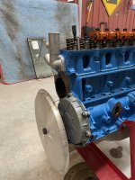
engine porn centerfold
Manton series 4 pushrods which have hard drawn tubes for guide plate use. 5/16 x .083 WallAlso I’m wondering who you guys use for pushrods?
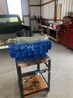
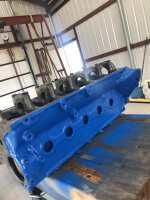
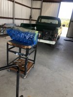
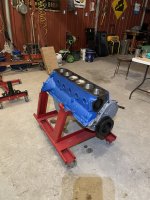
Looking good! What color blue is that?Just getting started putting the motor together. I know it’s been a while. I finally got all the parts together and in the shop. Also I built the shop. Now that I’ve got a good place and some time I’m gonna get started painting. Then it’s time to put it together.
It’s rustoleums Ford blue engine paint.Looking good! What color blue is that?
Stock rods. https://fordsix.com/threads/this-will-be-fun.81731/post-643798Which rods are you using? And why terminator instead of HP?
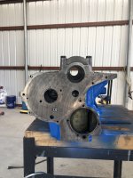
The pushrod needs to be the distance from the lifter to the rocker arm when the lifter is all the way down plus an additional .060" to .075" to preload the lifter plunger.Today I installed the head and now I’m looking at measuring for pushrods. I have a comp pushrod checker. I know I need to set the lash too. I’m kinda confused as to how I check the length without setting lash and vice versa. Setting the lash without the correct pushrod length.
Any thoughts?
I know I’m probably overthinking this. I’ve not done this sorta thing before and don’t want to make mistakes.
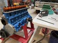
I’ve started to assemble the motor. Cam, crank, timing set is installed.
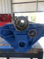
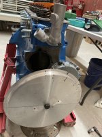
You need to be sure the cam is installed with the intake lobe center at 110 degrees ATDC.I didn’t use a degree wheel. All I did was install the cam and crank gears with the two dots lined up. I have the pointer cleaned up and ready to install but If I need to back up and do it differently I sure can. I’ve made a positive stop out of a spark plug that I was going to use to find mark top.
With the dial indicator on the end of the pushrod which is sitting on the #1-cylinder intake lifter (second lifter from the front), you should be able to turn the crankshaft clockwise to see when the lifter is up .050"I found tdc with a homemade wheel and stop. I loaded an old lifter with washers and slid into #1. I was going to use this and one of the old pushrods to check the camshaft timing with a dial indicator.