EEC-IV basics

Regarding your issue with the fuel pump relay; it could very well be more of a problem in the plug itself. I have seen the wiring insulation deteriorate and also the wire strands breaking causing the resistance to increase. Have you tried replacing the electrical connector to the relay?

S-659​

Electrical Connector​

STD

POP: D​

Per Car: 1​

Thanks for the suggestion. I have been through the fiel system as far as new pumps. And new sending unit. I also removed and re sealed the tank. I noticed that the factory wires at the plug are a bit worn. I was considering just running all new wires for the injection system from the relay.
While swapping to the more common configuration relay at the same time.
 
I have troubling questions.

Did the 351 and 460 ever get CFI, or did they go from VV carbs directly to mpfi?

Does the CFI run its two injection in perfect sync, or are they independently fired?

On the batch fire motors, how many batches are there? 2 or 3 for sixes, 2, 3, or 4 for V8s?

If the answer is 2 for both, than is there any actual difference between between the CFI ECUs and the batch fire ones, other than the fuel/timing tables on the ROMs and the amount of injectors on the output lines?

Will a 5.0 CFI run a 300 six with the appropriate sensors, distributor, and intake, like Clifford with a 2BBL adaptor? If yes, then will the Canadian Essex 3.8's CFI system run a 240 with said setup, seeing as there is less than 1% difference in them, displacement-wise?

Is the Essex 3.9 V6 setup speed density?
 
Last edited:
MechRick,

Thank you for posting all of this information! These older injection systems are simple and reliable but can be difficult to diagnose at times.
 
Head is spinning but I think I got most of it. This really helped lay out what I need to grab when I head back to the junk yard for my MAF conversion.
 
I've been wanting to do a thread on EEC-IV for a while now.
Have to add that this is an awesome info-dump. Thanks so much for taking the time to put it together in a digestible format. Info and data is always useful, but experience is what makes the info applicable and in-context.
Does the CFI run its two injection in perfect sync, or are they independently fired?

On the batch fire motors, how many batches are there? 2 or 3 for sixes, 2, 3, or 4 for V8s?
While the early EEC could be used for CFI/TBI, you "get what you get", and operational or tuning changes are both complex and limited. It has become far more common to use inexpensive aftermarket ECMs to configure setup and operation of both fuel and ignition in the best way for your use. Independent injector firing control, firing injectors at any crank angles you like, and how many times per-cycle you choose and test as best, e.g., 2 injectors, alternating, firing 3 times each per-cycle, for 6 evenly-spaced injections.

Like Starbucks and coffee, MegaSquirt started it all and many others are now filling the space of custom DIY EFI. 2-channel ECMs are under $100 (CFI or 3x2 MPFI and distributor), and 4-channel (paired MPFI injectors on 3 channels and waste spark coil packs) are under $200. They are also designed for user tuning with dashboard and tuning analysis programs (not a manipulation of the proprietary Ford or other system) that tune logically more like carbs, making better operation within grasp for the average hobbyist. Something to think about to make older but robust hardware such as the 2V CFI very useful.
 
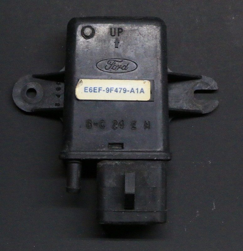
Ford decided to forge an unusual path when it comes to Manifold Atmospheric Pressure (MAP) sensors. Most manufacturers chose a simple 0-5v signal, with decreasing manifold pressure indicating less voltage at the sensor output. Ford used a frequency generator instead.

Ford uses a 5v input, and the sensor is grounded through signal return as other manufacturers. The output however, is a 5v square wave whose frequency varies with manifold pressure.

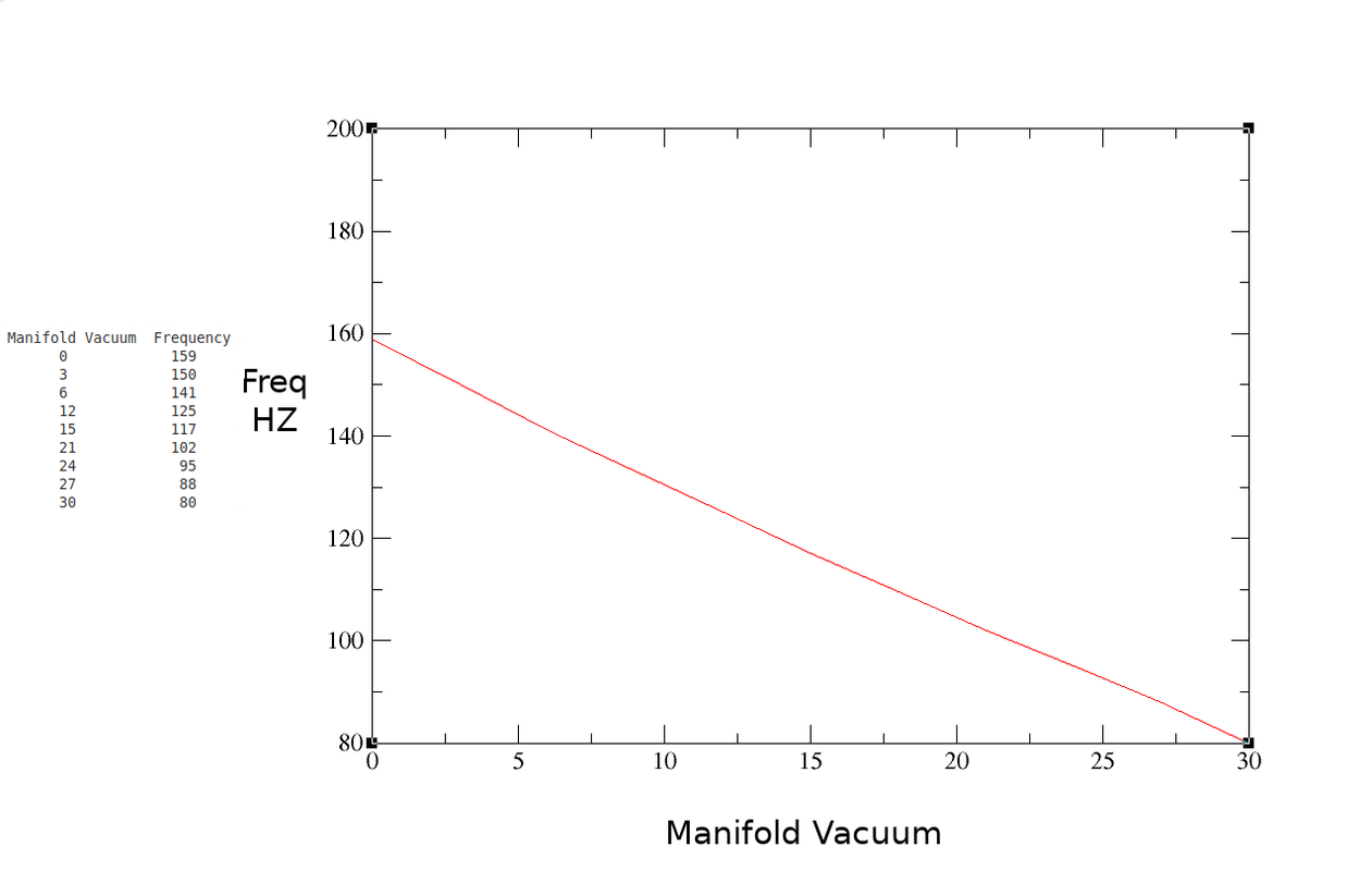
Typical sensor values will swing between approximately 100 HZ at idle and 151 HZ at wide open throttle. Accurate diagnosis requires a frequency meter. Nowadays they can be bought cheaply, back in the 80's they were prohibitively expensive for the average technician. We resorted to Ford's method for checking sensor output, which is setting a voltmeter to DC volts and looking for around 2.5 volts on the center MAP output pin (5 volts at a 50% duty cycle equals an average of 2.5 volts). This won't tell you the frequency of the signal, but will tell you if the sensor is completely dead.

Many MAP issues were actually vacuum issues. Hydrocarbon vapor can dissolve the potting inside the sensor, which can plug the vacuum hose. Rubber vacuum hoses crack and split, vacuum nipples on intakes plug with carbon.

A spare MAP sensor is something every Ford tech had in his toolbox for diagnosis.


MAP and BARO sensors are identical, BARO sensors will not have a vacuum hose attached to them. Be careful when looking at BARO PID's, as Mass Air vehicles may show the PID, but not have a BARO sensor installed. These vehicles will use WOT airflow data to calculate (infer) BARO PID data.
Looks like these can read up to 15psi of boost at 300mhz. It’s a hard coded limit in the ECM code for like 162mhz that looks it can be changed. Going to attempt a turbo eeciv tune this summer on my truck with this map sensor
 
Standard analog MAP sensors can use a tiny analog-PWM converter, making almost any MAP sensor usable. Inexpensive. Hit me when you get there,
 
What protocol does the EEC IV in a 95 Mercury Sable use? I ask because an OBD2 code reader I bought (along with a Ford 7-pin adapter) isn't connecting through the DLC. (I'm aware the car is OBD1, but I've heard that I SHOULD be able to use a reader or scanner with my adapter. ) It tries, there's a display on the reader while it does, but then it fails. And it's only doing that much in KOEO, not KOER. I would like to obtain a scanner, not just a reader, so I can turn off my Check Engine light after I replaced the coolant temperature sensor. (Disconnecting the battery, interrupting the KOEO test, and temporarily removing the EEC fuse have all been ineffective.) I used the DLC jump wire/counting flashes method and got a 116. I get a 111 after the engine warms up, but the light never goes out running and driving the car. Before buying another scanner I want to make sure it can handle the protocol my EEC IV uses.
 
I dont think ou ned a scammer at all to read the codes.
Mine is EEC IV with the two digit code system, 1988. I htin the later ones may have used the check engine code to flash the codes.

there is a youtube video just search for reading ECU codes. my suggestion is try watching a few as the process is easier to understand with a demo than just by reading the directions.

it will show you how to use a wire junmper and a test lamp, that's all you need.

i did buy a bosche code reader, it was in a discount bin for about 10 bucks and it helps a little just by being a bit easier to hook up but the codes youll get will be no different.


I personally found that getting the key off codes not so bad but when I got to trying to read the engine running codes, it wants me to turn the steering wheel put it in and out of overdrive with a button , step on the brakes, but on my truck the gear selector enguages overdrive. shoudl I put it in overdrive then? it wants me to floor the engine,, the problem I have is trying to understand the timing sequence.. when shoud I floor it?

in the one video I found hes in a pickup and loiking at his dash light and timing his own actions to that, but on mine I have the reader instaleld and so I need to leave the drivers seat to see it .. so maybe if you hook up the test lamp rather than use the bosche tool it makes it easier to see the flashing from the drivers seat.

I found it helpful to use a phone ot video the blinks it reports then its easier to later write them down ,, you can re-run the video to make sure you decipher the codes correctly.

the reader I have came with a booklet, ones later than mine may have 3 digit codes. I found the booklet so full of repeated safety info it was hard to follow. the sequence might be re-written so that it can be more easily followed maybe by going through with a highlighter and only highlighting the steps you actually need to perform..

having a real ford guy with experience leaning over your shoulder would be helpful.. If you don't have that the videos are quite helpful.
if you load the viseo on your phone then you can stop and start it and try to follow the sequence properly.

Ill admit I found doing it properly a little confusing, once you have the codes you can look them up. sometimes you may get codes that are not the cause but the result of an issue.

as an example it looks at wheather the EGR valve is reacting, the ecu sends a signal to the valve that redirects vacuum to the EGR valve then the EGR moves and it is sensed, the sensor then relays that info ( sensor blocked) back tot he ECU.. if the ECU doesnt; see the signal ( sensor blocked) i tmay cough up an error about the EGR valve.

The code isn't smart enough to know WHY the sensor didnt get blocked or unblocked , the cause could for example mean the valve isn't working , the EGR is stuck or the sensor that reports movement is unplugged. it could mena the vacuum isnt; being supplied to the vacuum valve so there is no vacuup to supply..

so as you decipher the codes also try to think what caused them.

so in this case you could replace the EGR then realize it is actually a problem wiht the sensor or maybe a problem wiht that vacuum solenoid that is directing vacuum to activate the EGR.. or maybe the vacuum hose that supplies vacuum isn't connected.. It could be caused by the vacuum hose fron the solenoid to the EGR had come off.. it could be a broken wire,. bad connector etc..

All the ECU really "knows" is it sent the 12 V signal to the vacuum solenoid and the inputs of the ECU did not sense the feedback from the position sensor had changed state..( as expected) then it barfs up a code.

I used that example as mine seemeed to report that and it seems like a common one.

Mechrick understands all of this a lot more throroughly so maybe thats just to be considered as my own findings.. with the 88 and stock ECU.

if you are trying to decipher codes from a different ECU maybe that should be it;s own post to avoid even more confusion? I can see this post being helpful for many , as Mechrick did add a lot of good detailed explanations. I found it very helpful.
 
Last edited:
I dont think ou ned a scammer at all to read the codes.
Mine is EEC IV with the two digit code system, 1988. I htin the later ones may have used the check engine code to flash the codes.

there is a youtube video just search for reading ECU codes. my suggestion is try watching a few as the process is easier to understand with a demo than just by reading the directions.

it will show you how to use a wire junmper and a test lamp, that's all you need.

i did buy a bosche code reader, it was in a discount bin for about 10 bucks and it helps a little just by being a bit easier to hook up but the codes youll get will be no different.


I personally found that getting the key off codes not so bad but when I got to trying to read the engine running codes, it wants me to turn the steering wheel put it in and out of overdrive with a button , step on the brakes, but on my truck the gear selector enguages overdrive. shoudl I put it in overdrive then? it wants me to floor the engine,, the problem I have is trying to understand the timing sequence.. when shoud I floor it?

in the one video I found hes in a pickup and loiking at his dash light and timing his own actions to that, but on mine I have the reader instaleld and so I need to leave the drivers seat to see it .. so maybe if you hook up the test lamp rather than use the bosche tool it makes it easier to see the flashing from the drivers seat.

I found it helpful to use a phone ot video the blinks it reports then its easier to later write them down ,, you can re-run the video to make sure you decipher the codes correctly.

the reader I have came with a booklet, ones later than mine may have 3 digit codes. I found the booklet so full of repeated safety info it was hard to follow. the sequence might be re-written so that it can be more easily followed maybe by going through with a highlighter and only highlighting the steps you actually need to perform..

having a real ford guy with experience leaning over your shoulder would be helpful.. If you don't have that the videos are quite helpful.
if you load the viseo on your phone then you can stop and start it and try to follow the sequence properly.

Ill admit I found doing it properly a little confusing, once you have the codes you can look them up. sometimes you may get codes that are not the cause but the result of an issue.

as an example it looks at wheather the EGR valve is reacting, the ecu sends a signal to the valve that redirects vacuum to the EGR valve then the EGR moves and it is sensed, the sensor then relays that info ( sensor blocked) back tot he ECU.. if the ECU doesnt; see the signal ( sensor blocked) i tmay cough up an error about the EGR valve.

The code isn't smart enough to know WHY the sensor didnt get blocked or unblocked , the cause could for example mean the valve isn't working , the EGR is stuck or the sensor that reports movement is unplugged. it could mena the vacuum isnt; being supplied to the vacuum valve so there is no vacuup to supply..

so as you decipher the codes also try to think what caused them.

so in this case you could replace the EGR then realize it is actually a problem wiht the sensor or maybe a problem wiht that vacuum solenoid that is directing vacuum to activate the EGR.. or maybe the vacuum hose that supplies vacuum isn't connected.. It could be caused by the vacuum hose fron the solenoid to the EGR had come off.. it could be a broken wire,. bad connector etc..

All the ECU really "knows" is it sent the 12 V signal to the vacuum solenoid and the inputs of the ECU did not sense the feedback from the position sensor had changed state..( as expected) then it barfs up a code.

I used that example as mine seemeed to report that and it seems like a common one.

Mechrick understands all of this a lot more throroughly so maybe thats just to be considered as my own findings.. with the 88 and stock ECU.

if you are trying to decipher codes from a different ECU maybe that should be it;s own post to avoid even more confusion? I can see this post being helpful for many , as Mechrick did add a lot of good detailed explanations. I found it very helpful.
Regarding the order of the steps for KOER, after the engine is warmed up - upper radiator hose hot - and the jump wire put in, the check engine light will flash half the number of cylinders. I have a 6 cylinder, so it flashes 3 times. Then you wait for a single flash which indicates it's ready. When you see it, goose the engine, press the brake pedal, and turn the steering wheel at least a 1/4 turn each way if not all the way. The codes may start flashing before you finish, but it'll go through them twice. Gotta be ready to write them down beforehand.
 
thanks for that, after I get three blinks and then a flash again goose it. step on brakes, turn laft, right , should I put it in gear to sense Overdrive? mine has no OD button for that. it has an auto trans and the shifter goes P,R, N OD, D ... then 2 and 1 I guess

what I can do is start the camera maybe tape cell phone so it sees the reader. maybe I can put it so I can see the blinks..
the reader has a switch for a beeper but it's a bit hard to hear it
over engine noise. I think switching it to "test" is the exact same same as installing the jumper.

I bought a 30 dollar boroscope with a super long cord I guess I could just use that to view the reader from the drivers seat. or extend the wires to a little test lamp so I can see it without using the reader. then I could see that blink , after the 3, with a foot ready over the gas pedal.
do you think the order matters? gas, brake, steering, then OD? I wasn't sure if the sequence of operations is important to the outcome of the test. I thik last time I tried I got a code that said "operator error."
That's the order I'd do it unless someone else knows something different. My car has overdrive, but I had never heard of that step and it actually doesn't seem to matter to getting the codes. I don't get an extra code relating to it. Maybe see if you can get away with skipping it like I've always done. I HAVE gotten extra codes if I skip the goosing and braking steps. I don't remember every getting one for skipping the P/S step.
 
That's the order I'd do it unless someone else knows something different. My car has overdrive, but I had never heard of that step and it actually doesn't seem to matter to getting the codes. I don't get an extra code relating to it. Maybe see if you can get away with skipping it like I've always done. I HAVE gotten extra codes if I skip the goosing and braking steps. I don't remember every getting one for skipping the P/S step.
I guess there is a switch probably near the shifter linkage, so it cant; start in drive, I bet that OD switch is incorporated. I guess its possible to jump those two wires to make it think it saw a button press
if it really wants a button press, Ill try what you suggest and ignore that step first. I dont know about the ford, my volvo has a relay involved and a 4th gear switch in a manual trans.. maybe with auto they didnt want people switching it in to overdrive in first or reverse. I have a volvo OD that someone snapped by ignoring the switch, Im not sure if its quite the same , in a volvo it has a solenoid to actuate OD and a pull in coil and both a holding coil in that.
 
Back
Top