Make sure that the rod oil spurt hole is on the passenger side when you assemble the piston to the rod.
You are using an out of date browser. It may not display this or other websites correctly.
You should upgrade or use an alternative browser.
You should upgrade or use an alternative browser.
The Opus 250 Rebuild
- Thread starter OpusTheTailGunner
- Start date
OpusTheTailGunner
New member
drag-200stang: "Make sure that the rod oil spurt hole is on the passenger side when you assemble the piston to the rod."
lavron: "had the machine shop install the pistons on the rods because he had the equipment to do it..."
After toying with the idea of creating a jig and hanging the rods on the pistons, I came to my senses and had the local machine shop do it. It was a bargain when I consider how much time I probably would have spent. I handed him a print-out of this from the shop manual when I dropped them off:
OpusTheTailGunner
New member
Bubba and Lavron,
One of the questions I asked Schneider was whether the cam came with the 4° offset and they confirmed that it did. I was figuring I'd replace the chain and stick with the factory cam and crank gears, but based on your posts, I'm reconsidering. If I go with the Cloyes Cam and Crank gears (thanks for the info!), it seems like the timing is going to be 4° early as a result. What's the solution to that when degreeing the cam? Slip the chain on the cam gear by one tooth?
Thanks,
Mike
Hi Mike, if your crank gear doesn't have any wear on then you could reuse it if you wanted however unless the engine was very low Milage it's going to have wear in the timing gears as well as a stretched chain you will see that as soon as you assemble the timing set as a loose chain. Your 1973 250 crank gear uses the same part number as the early 1969 to 1972 set, but check it very carfully if you see any wear marks in the gear teeth then it needs to be replaced. The cam gear needs to be the early gear so that the timing is set to straight up. Ford had 4 different sets of timing gears and two chains this is how they verified the cam timing on the later emissions engines to detune them.
You should still degree the cam to know we're it ends up during the install then you could adjust it some with an off set key. Moving the timing one full tooth is way to much change at around 13 to 15 degrees I would need to do the math to be more accurate. Our site member "Ehco1955" did a very good video on cam degreeing his 200 six watch it the principals are also the same for a 250 or any other small Ford six. This way you set the cam up by the manufactures recommendations. Best of luck.
You should still degree the cam to know we're it ends up during the install then you could adjust it some with an off set key. Moving the timing one full tooth is way to much change at around 13 to 15 degrees I would need to do the math to be more accurate. Our site member "Ehco1955" did a very good video on cam degreeing his 200 six watch it the principals are also the same for a 250 or any other small Ford six. This way you set the cam up by the manufactures recommendations. Best of luck.
Sorry I Totally forgot to put in the link to Ehco1955's cam degreeing video for you in my above post!
OpusTheTailGunner
New member
Nice video. Thanks! I'll have to queue up the whole series.
Yes all of the videos he made were very good and even though it's on a 200 six the techniques used will be quite semular to your 250 rebuild.
OpusTheTailGunner
New member
Hello All,
I'm a bit embarrassed that it's been 7 months since the last post. Part of the delay was the need to build the workshop where the engine build is taking place and part was just too many other projects taking priority. But things have stabilized and I'm back to slowly putting the engine together and learning lessons along the way.
Lesson #1: For slow builders like me, choose an assembly lube with some stickiness to it. I ordered Driven GP-1 assembly gel after watching this video:
Lesson #2: If something is binding, don't force it! I discovered this as I was installing the pistons in the block and rotating the crankshaft after every installation. First two pistons went in smooth and the assembly rotated easily. Hit the third one and it took way too much force to rotate it about 45 degrees. Stopped and assessed the situation. I removed the con-rod cap from the last piston, spun it around 180 degrees and retorqued it. Smooth and easy rotation after that. I didn't realize that there was a right way and a wrong way to install the caps. For reference, the internet figures it should take about 30 ft-lbs to rotate the crank and pistons with no cylinder head installed.
Lesson #3: Measure everything, because sometimes dimensions aren't what you planned. After installing the pistons, I noticed that they were protruding above the deck by about 0.010". This was surprising since my calculations had shown that they should be 0.050" down the bore. I measured an uninstalled piston assembly and compared it to the original assembly and sure enough, the new assembly is 0.16" longer than the old one and not the 0.10" longer that I thought it would be. The planned difference was based on the '86 2.5L (153ci) connecting rods and Silvo-Lite UEM-1120 pistons which together were supposed to be only 0.1" longer. So, my static compression ratio is now estimated at about 10 and not the 9 that I planned. Looks like I'll be running a little higher grade gasoline.
Lesson #4: Check to see that your camshaft comes with the cam gear pin installed. If not, just order a new one since they cost a couple of bucks and its easier than trying to yank the old one out of the old cam.
Lesson #5: Check that your camshaft spins freely before you install the crankshaft and all the pistons. This is where the build stands right now. I installed the cam gear pin, put the gear on and then attempted to spin the cam in order to line up the timing mark with the crank gear before putting on the timing chain. Aaaannndd it won't budge a millimeter, even with a long breaker bar torquing on the nut.
From what I understand, the seized cam could be a bad bearing, too much lube in the end bearing or some debris caught somewhere. I remember the cam went in easy through the first three bearings, but I did have to tap it into place with a wood block and hammer when I got to the last one. Looks like I'll be taking it out and seeing if anything looks obvious. Of course, any experienced thoughts about what could be going on are welcome.
-Mike
HI Mike, glad to hear your back on the assembling of your 250. X2 on lesson #4 yes but it's still better to remove the pin so you can get the camshaft spacer ring off to reuse on your new camshaft doing that also fixes the trouble your having in lesson #5. This happens so frequently it's like clockwork that people forget that they need to remove the old cam spacer ring off the old camshaft. In the recent past it was also very hard to find another spacer ring however if you no longer have the old cam you can now buy a new ring from Vintage Inlines V. I. I think it's about $25.00 though. When you take the cam timing gear off to install the spacer examine the cam thrust plate for damage and or scoring if you really cranked down on the cam bolt or put a lot of torque on it to try and turn the engine over there is a good chance that thrust plate is going to be damaged too and may need to be replaced. Then once you have the cam spacer ring installed on your new cam and everthing reinstalled you should be good to go again. By the way on the Ford Connecting Rods they have ID numbers stamped on them that will tell you which coralate to the blocks cylinder number that the Rod & Piston orginally came from, and also note that those numbers need to be on the same side of the Rod for you to know that the Rod caps are installed correctly. Best of luck on your 250 engine rebuild.
OpusTheTailGunner
New member
"Spacer?"
[runs out to garage, looks at shop manual, spots "spacer" in parts diagram behind thrust plate, inspects old camshaft, curses and slaps forehead, removes old pin with vise grips, and pops the spacer off]
Lesson #6: There's a spacer that sits behind the thrust plate that you need to remove from the old camshaft!
Pmuller and Bubba - Thank you! I owe you a beer or something. Don't know how I missed that piece of information when reading through the posts. The Ford shop manual assembly procedure sure doesn't mention it. And there's no apparent damage to the thrust plate. Fortunately, I recognized there must be a problem with only a modest amount of torque applied to the cam bolt.
Update a few hours later: put the spacer on the new cam, retorqued the thrust plate bolts and now everything spins freely. Cam and crank gears are now on with the timing chain, so I can start looking at the valve timing and confirm the cam profile.
And I looked at the rods and sure enough, there were the rod numbers right where they should be. I miraculously assembled 5 of them and got the orientation right and it was only the one that caused me trouble. Lesson learned.
Last edited:
That’s great  glad that there wasn’t any damage done.
glad that there wasn’t any damage done.The inside bevel on the cam sprocket spacer goes toward the cam journal...And while we are at it make sure that the two, screw in oil galley plugs are in place , one at each end of the block.
OpusTheTailGunner
New member
The inside bevel on the cam sprocket spacer goes toward the cam journal...And while we are at it make sure that the two, screw in oil galley plugs are in place , one at each end of the block.
Thanks - I saw that as I was taking it off so made sure to orient it correctly when it went on.
For the plugs, I see the one on the rear of the engine block:
But I don't see anything on the front of the block. Just this one on the driver's side under the freeze plugs:
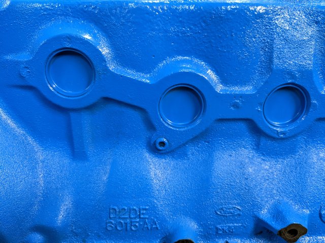
Is there another plug location?
-Mike
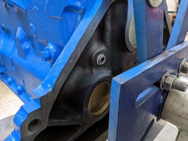
Yes at the front by the cam retainer plate , the sprocket may be hiding it.
OpusTheTailGunner
New member
I see it now. Yes, hidden behind the cam gear just above the thrust plate:

OpusTheTailGunner
New member
I spent some time this weekend degreeing the cam and have a funny newb story to go along with it.
After putting on the timing chain and the cam gear from the earlier generation (S414), I dig out an old lifter and sand the carbon off of it before cleaning, lubing and dropping it into the hole above the cam lobe. I find the pushrod and drop it into place and then track down a little curtain rod holder that I can slip over the pushrod and clamp down to keep the whole thing more or less stable. I get out the bridge and find TDC on cylinder number one and dial in the cam degree wheel to zero. I move the dial indicator to the top of the pushrod, watch a few Youtube videos to get the process down and walk through finding the center of the lobe lift. With that done, I go back and forth and calculate the number. It's about where it should be. Great! So I rotate the engine a few times to remind myself about the power stroke, the exhaust stroke and the intake valve opening point.
Except something's... a little... off.
The opening time seems odd. Almost like I'm watching...
Oh, Mother of Pearl, I've degreed the exhaust valve!
A quick confirmation on the cylinder head, and sure enough, I dropped the lifter into the first position and just ran with it. So for those others out there who are doing this for the first time: the first port and valve in the sequence is the exhaust port. The intake port and valve are in the second position.
Finally set everything up correctly and managed to achieve a camshaft intake valve position of 106.5 which is not far off the 108 Schneider said it should be. I'll double check everything later this week.
-Mike
Hi Mike how are you doing with your 250 build or is it runing now?
Similar threads
- Replies
- 8
- Views
- 1K
- Replies
- 26
- Views
- 3K