EEC-IV basics

MechRick

1K+
VIP
I've been wanting to do a thread on EEC-IV for a while now. It's just old enough and obscure that a thread with all the relevant bits in one place should make for a nice resource. I was a Ford dealer tech starting in '86, sticking with the brand until 1999, so these systems were my bread and butter at the start of my career.

I should mention briefly the predecessors to EEC-IV. It's a good time to insert the link to the Wiki:

https://en.wikipedia.org/wiki/Ford_EEC

EEC-III was the direct predecessor of EEC-IV. It was used in feedback carb and throttle body (CFI in Ford speak) systems. EEC-III used a crank-mounted sensor for RPM. The distributor only distributed spark through a wide body cap with internal routing to provide symmetry of spark plug wire routing. There were no sensors inside the distributor. ECM was under dash. The biggest failing to this system was the unsealed connectors between the crank sensor and ECM, and the harness routing in the vee between the intake and valve cover, an often oil-soaked area (What? Fords leak oil?).

Ford also used MCU (Microprocessor Control Unit) on various vehicles until the mid-late '80's. It was a very simple system, controlling a feedback carb and emissions systems on the vehicle. The only timing control was the ability to retard spark via the Duraspark module. This system hung around and was offered parallel to EEC-IV in police and emergency vehicles. It's advantage was the ability for the vehicle to run with the ECM unplugged, useful in that role. You can tell MCU from EEC-III (besides the goofy EEC-III distributor cap) as the MCU ECM was under the hood.

The single easiest indicator you have an EEC-IV system is the presence of a TFI-IV ignition module. Early cars had them mounted to the distributor, later ones moved to a remote heat sink. I won't go into TFI issues with this post, as it's easy enough to substitute a known good module for diagnosis. I carry a spare module and wrench in all my TFI-equipped vehicles.

The earliest EEC-IV systems (early 80's) were feedback carb or CFI. CFI was a short-lived engineering bridge between carbs and port injection. By '86, the 5.0L was port-injected and SEFI (Sequential Electronic Fuel Injection). These cars were a significant step forward in driveability and power/torque production compared to the CFI/carb vehicles they replaced. Trucks used a similar system that was bank-fired instead of SEFI, and used higher fuel pressure. There were only two significant issues with the early port-injected cars/trucks. First was oil consumption. Port injection allows a high flow PCV valve, so Ford went to low tension piston rings with the port-injected engines. It took a few years to get the bore/ring interface correct, and it's not uncommon for the early ones to burn a quart of oil every 1,000 miles. the second was injector clogging. It was found that fuel would hang on the injector tip after shut down and evaporate, leaving deposits on the tip of the injector. Flow would degrade over time requiring injector cleaning or replacement. Ford scrambled to update the design of the injector to move the pintle up into the body of the injector which helped, but in 1988, ethanol was approved as an additive in pump gas. Injector problems went away after that.
<to be continued>
 
Last edited:
Connectors:
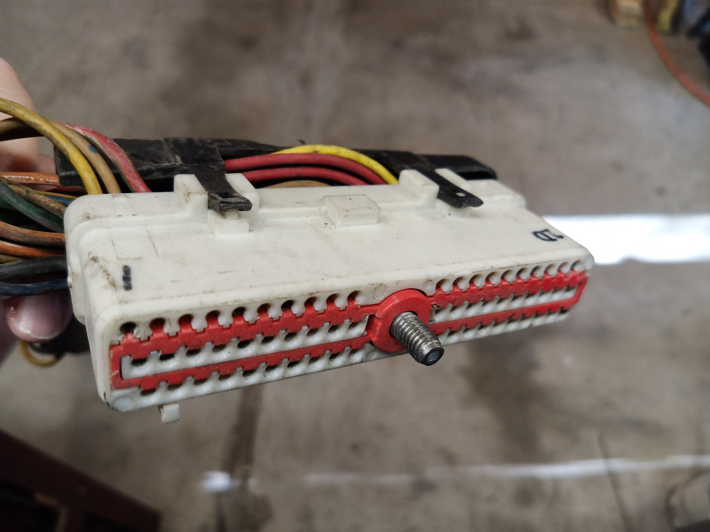
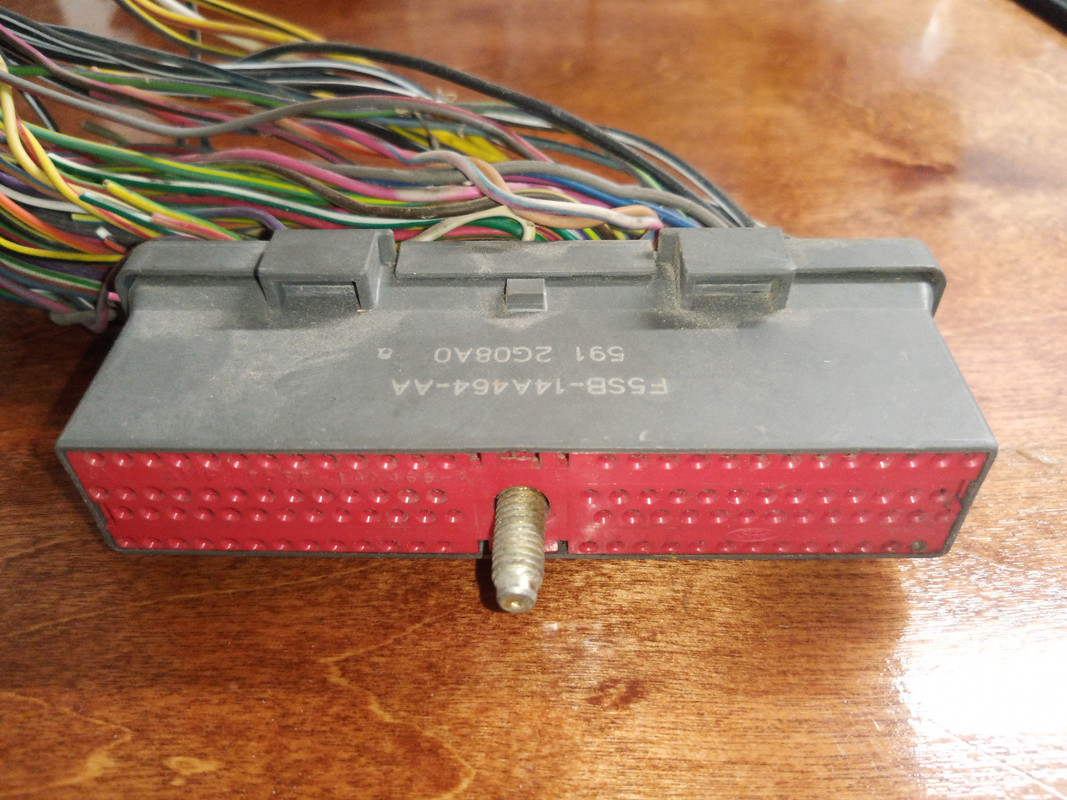
The ECM attaches to the harness with a 60 pin connector drawn/held in place with a 10mm bolt. Trucks are placed on the left side of the under dash and the harness bolt is accessed from under the hood below the brake booster. Cars are almost always in the passenger kick panel.

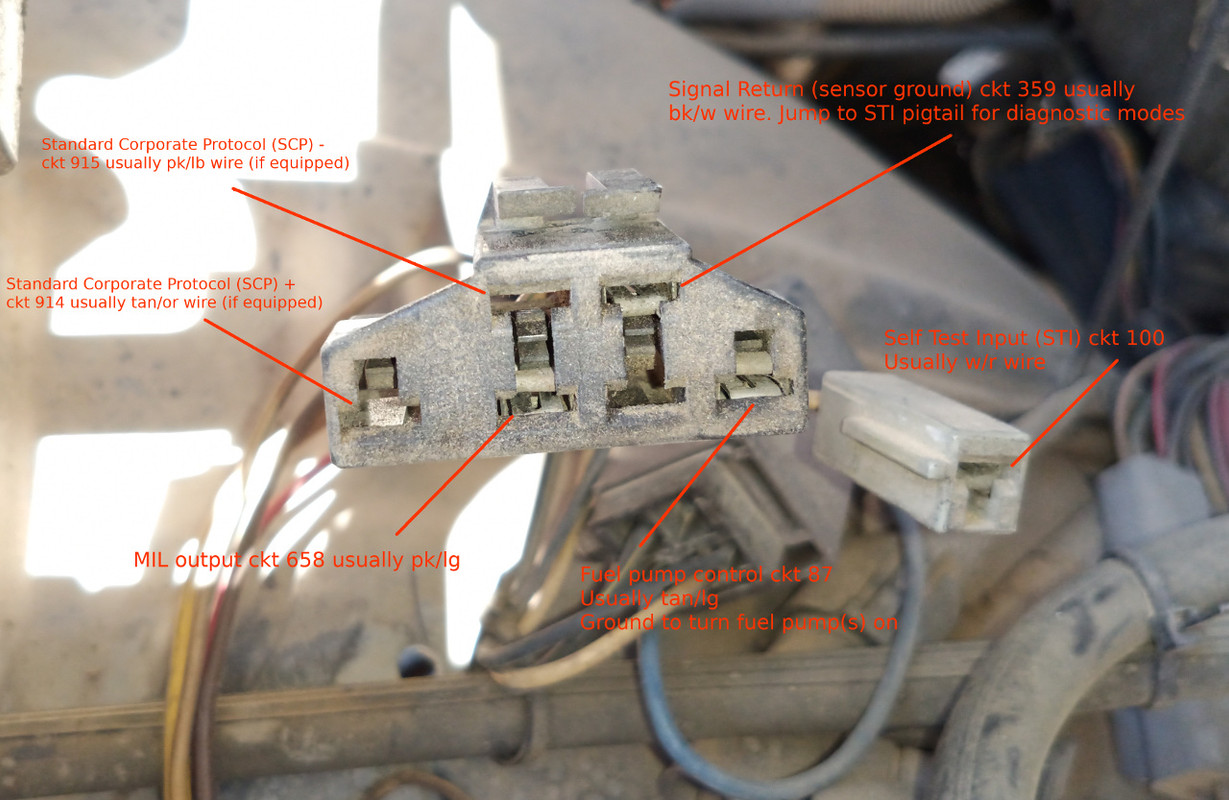
the Data Link Connectors (DLC) are under hood and move around depending what you are driving. ABS and MCU connectors look the same as the EEC-IV DLC, so be careful. In general, if the DLC is red in color, you've got the wrong one, or have a MCU system. DLC is gray/black in color for EEC-IV.

-Here is the one off my '88 F250. It looks pretty ragged and dirty, you'd look sad too if you were forced to ride around under the hood for 33 years and 140,000 miles.

 
Last edited:
Speaking of dirty connectors, it's a good idea to clean them before a self test. There are two methods of erasing fault codes with EEC-IV, disconnect the battery, and interrupt the KOEO self test in the middle by disconnecting the jumper wire. A dirty connection may accidentally erase your codes before you read them.

To initiate a self test, jump STI to SIG RTN. This essentially grounds the STI pigtail and puts the ECM in self test mode. There are several self test modes, I'll cover them in a bit.

The factory tools started with the Star tester, then the Super Star tester. Both of these tools were code readers only. The new Generation Star Tester (or NGS for short) made by Hickok for Ford, was the first tool that would read live PID (Parameter IDentification) data from the ECM. I owned a NGS for about four years. They are a neat tool, and if Hickok had released software for use with more manufacturers, I would have held on to it longer. The next pieces of diagnostic equipment were the SBDS (Service Bay Diagnostic System) and WDS (Worldwide Diagnostic System). THE SBDS was a big, roll around machine. It was short lived, and the laptop-based IDS/VCM became much more popular after a few years.

The Star-Type testers had a big button in the middle and a numeric display. Latching the big button jumped STI to SIG RTN.

You can duplicate the function of a star tester with a jumper wire (and perhaps a test light on the very early vehicles). Jump STI to SIG RTN with the key off. If the vehicle is equipped with a check engine lamp (very early ones were not, and Ford caught considerable flack from the EPA because of it), turn the key on and count the MIL lamp flashes as they occur. If yours doesn't have a MIL, clamp the alligator clip of a test lamp (or the positive lead of a volt meter) to battery positive. Stick the probe of the test lamp (or an analog volt meter negative lead) in the DLC MIL output slot. Count the test lamp flashes or volt meter needle swings. The MIL output terminal wires go two places. One wire goes to the ground side of the MIL bulb in the cluster (if equipped), and the other to the ECM MIL pin. Early vehicles only have the ECM connection. The ECM grounds this pin to turn on the MIL or flash your test lamp.

You'll notice two Standard Corporate Protocol (SCP) positions in the DLC above. Later EEC-IV systems had the ability to output live data over these circuits. Vehicles that have this capability will usually have Mass Air sensors and 3 digit fault codes. Alas, my old truck uses a MAP sensor and does not have these circuits.

Another useful circuit is the fuel pump relay connection. By grounding this slot, the fuel pump(s) will turn on, even with the key off. Useful for checking fuel pressure or draining fuel tanks, or perhaps checking for power at the pumps.
 
Last edited:
Test modes:

I'll start with the old two-digit speed density system first, there are only three test modes. KOEO (Key On Engine Off), KOER (Key On Engine Running) and wiggle test.

The KOEO test checks for hard faults and intermittents (AKA Continuous). The format is:

Hard Fault|Separator|Continuous

Pass codes flash 11. The Separator is a single flash that we call the number 10 for some unknown reason. All codes repeat once the codes string is flashed once. A full pass would flash 11|10|11 and would look like this:

Flash, flash, pause. Flash, flash, long pause. Flash, long pause. Flash, flash, pause. Flash, flash.

Now let's pretend we have a hard fault with the EGR position sensor. Code 31 indicates the at rest voltage from the sensor is below normal.

Flash flash flash, pause. Flash, pause. Flash flash flash, pause. Flash, long pause. Flash, long pause. Flash flash flash, pause. Flash, pause. Flash flash flash, pause. Flash.

You should read that as 31|10|31. Note the code 31 also appears to the right of the separator in the continuous portion. This will usually be the case with hard faults.

Now let's pretend the EGR valve position sensor hiccuped once on a test drive, then healed itself.

Flash, flash, pause. Flash, flash, long pause. Flash, long pause. Flash flash flash, pause. Flash, pause. Flash flash flash, pause. Flash.

This reads 11|10|31.

Ford's stance on diagnostic direction is to chase hard faults first. If there are no hard faults, but you have continuous codes (or a pass code) do a KOER (Key On Engine Running) test.
 
Last edited:
The KOER test requires the engine to be warm. Run the engine until the upper hose is warm to the touch. Shut her down and set up your jumper and test lamp. Make sure all accessories (A/C, radio, lamps, etc.) are off.

-Start the engine. As soon as the engine starts, the idle will raise and the MIL/test lamp will flash the engine identifier. This will be half the number of cylinders, for instance, a 4.9L will flash 3 times. As this is happening:

Clutch to the floor, if equipped.

Mash the brake pedal to activate a brake pressure switch or brake lamp circuit, if equipped.

Turn the steering wheel 1/4 turn left and right to activate the power steering pressure switch, if equipped. Note the wheels must be on the ground for this to work.

Cycle the overdrive cancel switch off then on, if equipped.

You might be thinking: How will I know if any of this is equipped? Simple answer, just run through them all, and you'll have all the bases covered.

After that, the EEC-IV ECM will look at data, open and close various valves (when it opens the EGR valve, you'll think the engine will stall, but it probably won't). It may want to look at the TPS (Throttle Position) sensor. If it does, you'll get a single flash, and you must stab the throttle immediately to prevent false TPS codes from tripping. Miss any of these user inputs and false codes may result. If so, just repeat the test.

It will then either flash a pass code (Flash, flash, pause. Flash, flash), or fault codes. Let's say the running test found that bad EGR position sensor. If so, after the engine idle comes down, it should give you:

Flash flash flash, pause. Flash, pause. Flash flash flash, pause. Flash.

The wiggle test is designed to find bad connections. You'll hear me (not literally, of course) use the term 'latch' when talking about initiating a self test. It's left over terminology from that big latching button on the Star testers. It simply means jumping STI to SIG RTN at the DLC. You enter the wiggle test by turning the key on, latching the DLC, wait ten seconds and unlatch, then relatch the jumper.

-What happens at that point is the EEC-IV ECM will look at the electrical status of all inputs and outputs. The tech is supposed to start wiggling harnesses and connectors under the hood, and if the EEC sees any electrical status change, will ground the MIL output to let you know you are close. The Star testers had a buzzer to make this test even easier, but it's doable if you are watching a test lamp bulb while you are wiggling.

Here's a handy link of code descriptions. In general, lower numerical codes are more important and have a better chance of stranding you.

https://www.troublecodes.net/ford/eec-iv/

<to be continued>
 
Last edited:
The EEC will repeat strings of codes. Let's say you have these hard faults: 12, 31, 41, 62. The EEC will flash all of those codes, then repeat the entire sequence. This is nice, because if something interrupts your concentration while focused on the test lamp, you can verify on the repeat. Once codes are repeated, it will move on to the separator, then flash all continuous codes, then repeat them.

Here is a shot of the 60 pin from my Bronco. Note I've indicated the pin numbers with a marker. You can also remove the black plastic shield and read the numbers off the back of the connector.


Here's an EEC-V 104 pin connector for comparison. Both connector styles are very robust, and we didn't see many issues at the connector compared to other manufacturers.

 
There is one more diagnostic mode available that only applies to SEFI vehicles. Ford jumped on the SEFI bandwagon early (1986). There is a cylinder contribution test built in to the EEC-IV ECM on all SEFI vehicles. You access it by:

Perform a KOER test. At the end of the test, after the last continuous code is displayed, momentarily raise the idle speed to 1500-2000 RPM and release the throttle. You've just instructed the EEC to disable the injectors one at a time and record the RPM drop on each cylinder. You'll hear the idle come up, and after a few seconds to insure the idle is stable enough to perform the test, the EEC will kill each cylinder. At the end of the test, if one cylinder's RPM did not change (enough), the ECM will flash the number of the non-contributing cylinder. For instance, if it's cylinder #3, the EEC will flash 3 times. If there is more than one cylinder, the next dead cylinder will be flashed out. If it passes this test, it will flash 9 times.

-You can repeat the test, and on each consecutive go 'round, the ECM will narrow it's tolerance window for a weak cylinder.

EDIT: The easiest way to tell if your Ford is SEFI is look at the injector wiring. Of the two wires going to each injector, one is the VPWR 12 volt wire that powers up at key on, usually red in color. If you have a SEFI vehicle, the remaining wire of each injector will be a different color. SEFI vehicles require a driver circuit for each injector, while bank-fired EEC-IV can trigger all injectors with 3 wires, regardless of the number of cylinders.
 
Last edited:
On to three digit fault codes.

These systems added several diagnostic modes, the most useful of which is datastream capability. Ford shied away from giving techs this ability for years, relying on the infamous 'H' manual for diagnosis. As the systems became more complex, datastream and additional modes were added, probably because they were time savers in diagnosis. Time is money, and less warranty time means you don't have to pay your techs as much.

Code output is similar, the numbers are grouped in threes instead of twos. A system pass would be: 111|10|111. Examples of three digit fault codes are in the link above.

Most vehicles that have a Mass Air Flow Sensor will be three digit fault code systems with data capability. Some notable exceptions are 5.0L Mustangs, and first generation 3.0L Probes (Mass Air, no datastream).

Another added mode was an idle check procedure to correctly set throttle plate angle. If incorrect, idle-related fault codes can trip.

-To access, perform a KOER test, after last code is displayed/flashed, unlatch and relatch STI to SIG RTN. The ECM will command the IAC to a fixed value and look at the idle speed.

If the idle is high, the test lamp or MIL will flash fast.

If the idle is low, the test lamp or MIL will flash slow.

If the idle speed is within range, the test lamp/MIL will be on solid.
 
Last edited:


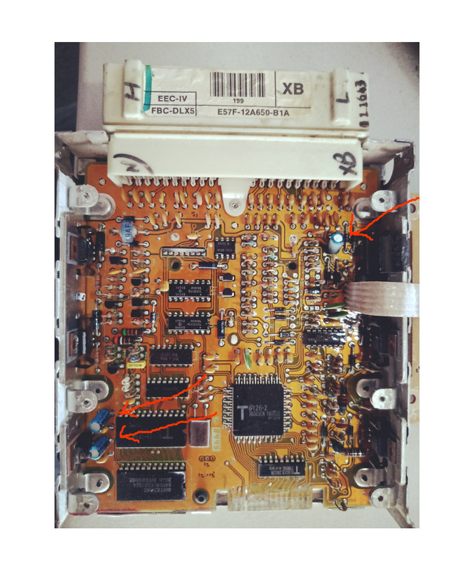
Typical EEC-IV ECM/PCM. This one happens to be for a feedback carburetor application. Ford's ECM's are extremely rugged. There was a running joke at the dealer when diagnosing a concern with the 'H' manual, if you reached the end of the flow chart and the recommendation was ECM replacement, start over from step one because you missed something. In seventeen years with Ford, I've only replaced two due to failure, and one of those had a screw drilled right through the middle of the circuit board (body shop deal. And it ran!).

Most of these ECM's are getting up in years now, and an increasing problem is electrolytic capacitor failure. If you have a strange driveability issue and normal troubleshooting doesn't find it, remove the ECM and pop the cover off. ECM's have different layouts depending on the application, so the number of electrolytics will change, but they all have at least a few. Failure mode is swelling and leaking the white dielectric compound on the circuit board.

 
woodforest national bank locations

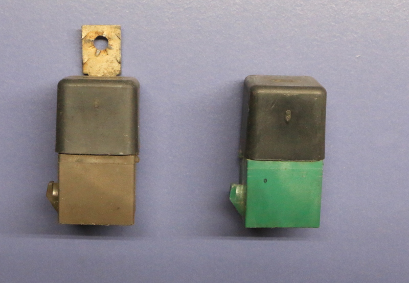
On the left is an EEC power relay. On the right is a fuel pump relay. EEC power relays are brown from the factory and fuel pump relays are green. Aftermarket replacements are usually gray. It's important to use the correct relay as there are often circuit protection diodes inside them to keep back EMF from damaging the ECM.

The EEC power relay is turned on by ignition switch power in run/start. The relay coil is always grounded. Once energized, it supplies power to the ECM and all of it's outputs (injectors, solenoids, etc.). This the VPWR circuit, circuit 361, usually a red wire.

The coil of the fuel pump relay is grounded by the ECM to turn the pumps on.
 
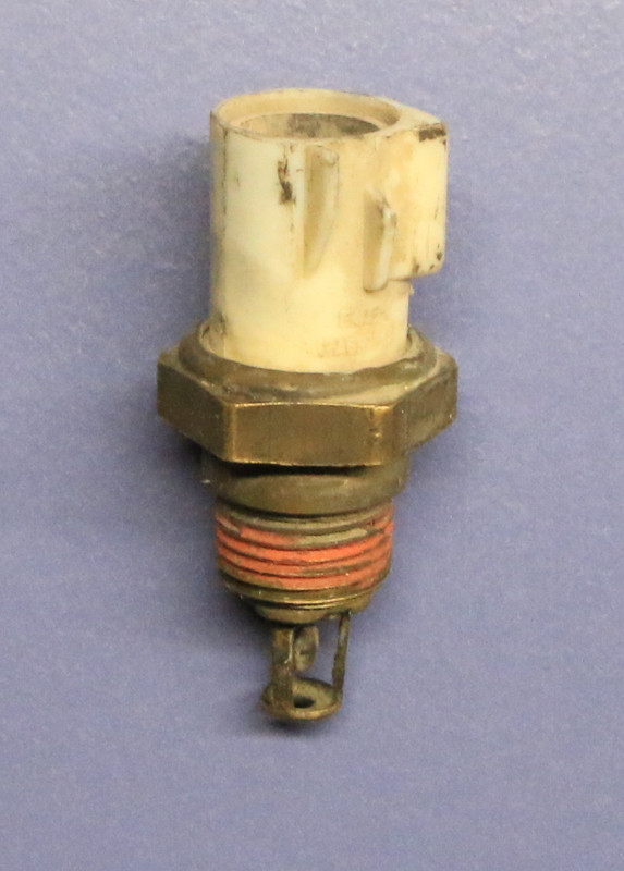
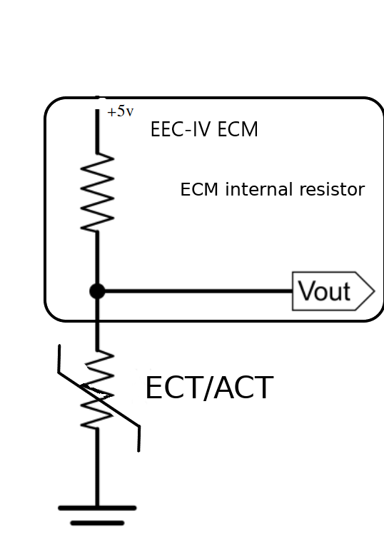
The Engine coolant temperature sensor (ECT) and intake air temperature sensor (ACT) are both thermistors. They work on the principle of a voltage divider. Inside the ECM is a fixed resistor supplied with 5 volts from the ECM's internal voltage regulator. The other end of the resistor is the sensor input. The ACT and ECT's resistance changes with temperature, and are both grounded to signal return in the ECM. As the ECT/ACT resistance decreases, it pulls the internal sensor input closer to ground.


The ECT and ACT look similar, with the thermistor bulb visible on the ACT and enclosed for use in coolant. One possible failure of the ACT is carbon/sludge buildup on the thermistor tonsil, resulting in start/stall/hesitation concerns.
 
Last edited:
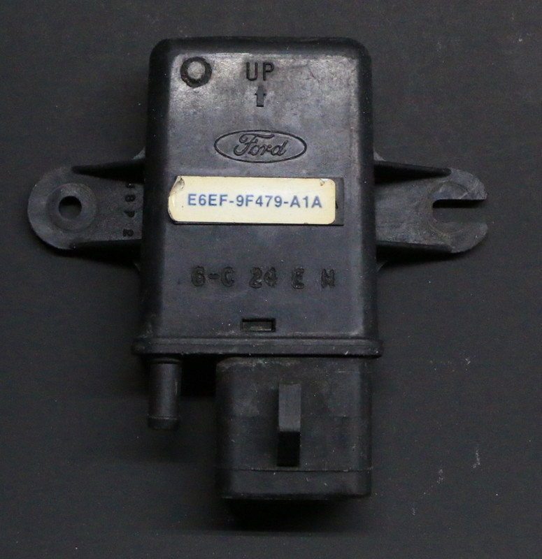
Ford decided to forge an unusual path when it comes to Manifold Atmospheric Pressure (MAP) sensors. Most manufacturers chose a simple 0-5v signal, with decreasing manifold pressure indicating less voltage at the sensor output. Ford used a frequency generator instead.

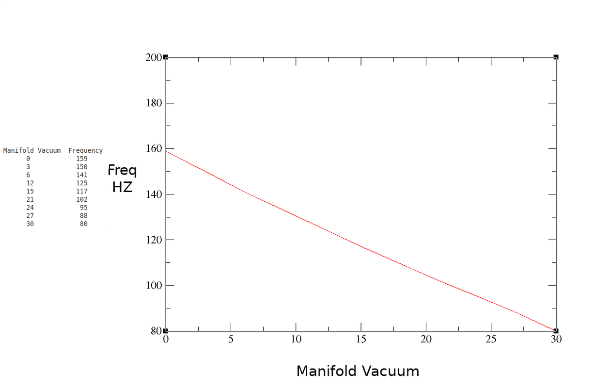
Ford uses a 5v input, and the sensor is grounded through signal return as other manufacturers. The output however, is a 5v square wave whose frequency varies with manifold pressure.

Typical sensor values will swing between approximately 100 HZ at idle and 151 HZ at wide open throttle. Accurate diagnosis requires a frequency meter. Nowadays they can be bought cheaply, back in the 80's they were prohibitively expensive for the average technician. We resorted to Ford's method for checking sensor output, which is setting a voltmeter to DC volts and looking for around 2.5 volts on the center MAP output pin (5 volts at a 50% duty cycle equals an average of 2.5 volts). This won't tell you the frequency of the signal, but will tell you if the sensor is completely dead.

Many MAP issues were actually vacuum issues. Hydrocarbon vapor can dissolve the potting inside the sensor, which can plug the vacuum hose. Rubber vacuum hoses crack and split, vacuum nipples on intakes plug with carbon.

A spare MAP sensor is something every Ford tech had in his toolbox for diagnosis.


MAP and BARO sensors are identical, BARO sensors will not have a vacuum hose attached to them. Be careful when looking at BARO PID's, as Mass Air vehicles may show the PID, but not have a BARO sensor installed. These vehicles will use WOT airflow data to calculate (infer) BARO PID data.
 
Last edited:
Ford decided to forge an unusual path when it comes to Manifold Atmospheric Pressure (MAP) sensors. Most manufacturers chose a simple 0-5v signal, with decreasing manifold pressure indicating less voltage at the sensor output. Ford used a frequency generator instead.

Ford uses a 5v input, and the sensor is grounded through signal return as other manufacturers. The output however, is a 5v square wave whose frequency varies with manifold pressure.

Typical sensor values will swing between approximately 100 HZ at idle and 151 HZ at wide open throttle. Accurate diagnosis requires a frequency meter. Nowadays they can be bought cheaply, back in the 80's they were prohibitively expensive for the average technician. We resorted to Ford's method for checking sensor output, which is setting a voltmeter to DC volts and looking for around 2.5 volts on the center MAP output pin (5 volts at a 50% duty cycle equals an average of 2.5 volts). This won't tell you the frequency of the signal, but will tell you if the sensor is completely dead.

Many MAP issues were actually vacuum issues. Hydrocarbon vapor can dissolve the potting inside the sensor, which can plug the vacuum hose. Rubber vacuum hoses crack and split, vacuum nipples on intakes plug with carbon.

A spare MAP sensor is something every Ford tech had in his toolbox for diagnosis.


MAP and BARO sensors are identical, BARO sensors will not have a vacuum hose attached to them. Be careful when looking at BARO PID's, as Mass Air vehicles may show the PID, but not have a BARO sensor installed. These vehicles will use WOT airflow data to calculate (infer) BARO PID data.
So that is why I couldn't use the Ford MAP sensor with Microsquirt! Nice to know in retrospect.
Do you know if the frequency MAP sensor are more accurate and or reliable than the resistance ones most every other (gm) maker uses? I haven't had a Ford one fail, but then again, I've only for sure seen one of the resistance units cease communicating. As you said, it's usually failed vacuum lines, grommets, or connectors.
 
Do you know if the frequency MAP sensor are more accurate and or reliable than the resistance ones most every other (gm) maker uses?

I don't have the official version, but I think that's it.

If you think about it, any resistance in the 5v supply voltage (VREF) or the ground circuit (SIG RTN), will change the voltage output of an analog MAP sensor. On a speed density system, the MAP is the sensor that will affect fuel delivery to the most significant degree.

-Interestingly, GM used the same frequency generating principle on some of their Mass Air sensors, arguably for the same reason.
 
Makes total sense. My resistance MAP sensor is soldered to the ECU board, with a long vacuum hose through the firewall.
Speed of sound lag is still less bad than speed of corrosion!
 
Thick Film ignition, AKA TFI-IV:

EEC-IV and TFI-IV are symbiotic, and were ushered in at the same time. Since the ECM now controls ignition timing, TFI-IV distributors will not have a vacuum advance. Early ignition modules were mounted to the distributor, later ones moved to a heat sink somewhere under the hood.

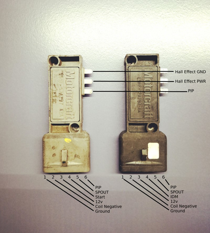
Here are examples of a push start module and a CCD (Computer Controlled-Dwell) module, both distributor-mounted versions.

cardio for bad back

The original modules were all push start and gray. The term 'push start' means the module, when seeing start voltage on pin 4, will 'push' more dwell to the coil while the engine is cranking, to aid in starting. Dwell is otherwise controlled internal to the ignition module and increases with RPM.

CCD modules came about later, were black in color, and had dwell controlled by the SPOUT signal from the ECM. The rising edge of PIP/SPOUT causes the ignition module to fire the coil, and the falling edge of spout controls dwell.

The two ignition modules are not interchangeable, but if you do, the engine will run, and trip Ignition Diagnostic Monitor codes.
 
PIP- Profile Ignition Pickup- This is a square wave signal generated by the hall effect sensor in the distributor.

SPOUT- SPark OUT- This signal is an ECM-modified version of the PIP signal fed back to the ignition module to adjust timing (and dwell with CCD).

12v- Voltage in for the ignition module and hall effect. Typically shared with the same source as ignition coil positive voltage.

Coil Negative- Ignition module grounds this circuit to initiate coil saturation, and releases it for spark.

Ground- The ground circuit for the ignition module and hall effect.

Start (on push start modules). Voltage from starter solenoid to increase dwell for starting.

IDM (Ignition Diagnostic Monitor)- Pin 4 on CCD modules, will go to the ECM directly from the coil negative terminal on push start systems. IDM is a way for the ECM to know if a spark event was requested, but not provided by the ignition coil. If a SPOUT signal went out, but there wasn't a matching IDM pulse, codes will store in the ECM. IDM works off the principle that a flyback voltage is produced by coil primary windings when the circuit is released. This is a high voltage spike that is damped with a resistor and fed back the the ECM, and helps to diagnose misfires.

Here's Xctasy's excellent TFI-IV writeup:
https://fordsix.com/threads/understanding-standard-and-signature-pip-thick-film-ignition.81515/

And more TFI-IV information in this thread:
https://fordsix.com/threads/cam-sensor-for-megasquirt-or-eqv.75607/#post-582202
 
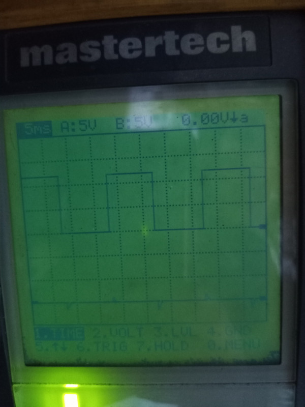
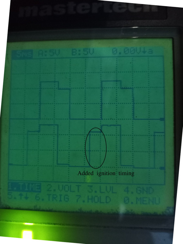
Here are some DSO waveforms of PIP and SPOUT taken from my 1988 F250. The first is PIP with the SPOUT connector unplugged, as if to set ignition timing.

upload pic net

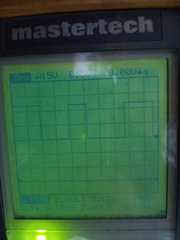
The next image is the same waveform, taken a few seconds later. Note the narrow waveform. This tells me the vane cup on this distributor has a narrow vane for use with SEFI, even though this particular truck is bank-fired.


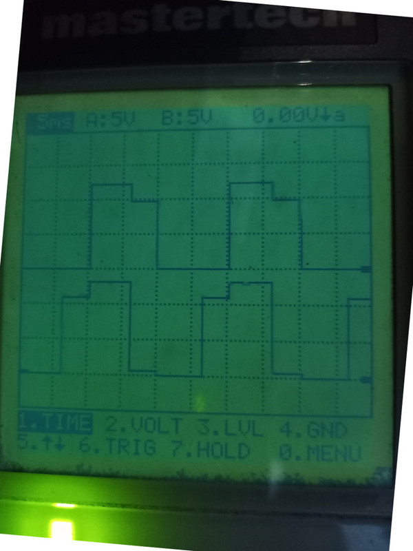
Now let's plug in the SPOUT connector so we can get a look at SPOUT. PIP signal on the top of the screen, SPOUT on the bottom.


Now things are getting interesting. Notice the notches generated in both signals. Remember, the ignition module fires the coil on the rising edge of SPOUT, and if SPOUT is not present, the module uses PIP instead. The left edge of PIP is base timing and is fixed by the distributor location. Draw a line straight down from the left edge of the PIP signal, and you can see the remnant of PIP in the upper portion of SPOUT. However, the ECM has added everything to the left of that point in the SPOUT signal. This is what adds ignition timing advance. Notice also that PIP is affected, and has a notch on the right side.


By stabbing the throttle, you can make the notch in SPOUT grow wider and narrower as the ECM manipulates timing to suit conditions.
 
Last edited:
Excellent write up! Great information and very well explained. I got more information about these EEC IV systems after reading this than a decade of wrenching, Haynes manuals and google combined!
 
Back
Top