EEC-IV basics

Thanks, Wesman. It's my sincere hope this information helps people fix these vehicles and keep them on the road.

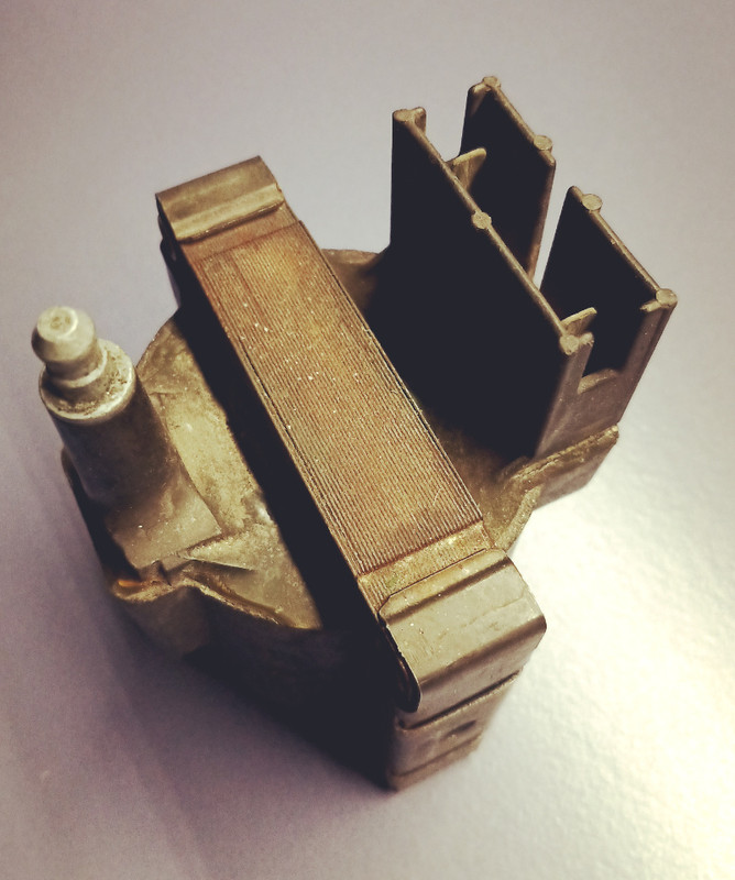
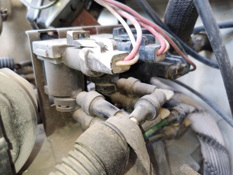
Another sure sign you have an EEC-IV is the presence of an E core ignition coil instead of a Duraspark barrel coil. E core coils are named for the layers of ferrous plates shaped like an 'E' and stacked together with wire coiled through the legs. E core coils are generally reliable, and since '86 I've only replaced a handful. The connection to key power and module is unsealed and can cause issues, but the connector pigtail is available and the terminals can be cleaned in the event of misfires. A little dielectric goes a long way.


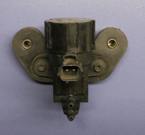
I should briefly talk about TFI issues. As we all know, heat is the nemeses of TFI modules. As I mentioned earlier, I carry a spare module, just as I carried a backup ballast resistor in all the vintage Chryslers I've owned. It's the reason Ford moved them to heat sinks (well, that and the class action lawsuit). I've had one die on me right in the middle of the Spaghetti Bowl (Las Vegas) on a very busy day in my Mustang and had to scramble to get the thing to the side of the road in one piece. However, that's the only time it has happened, and where I live 115 degrees F is normal. Many TFI problems can be eliminated by periodically removing the TFI, cleaning off the old dielectric and reapplying new.

I come from the age of bias ply tires, such on the road drama was normal back then, so that sort of thing typically doesn't freak me out.
 
Throttle Position Sensors were 0-5v potentiometers. Closed throttle voltage output is usually just under 1v. TPS's will have an operating range. If the sensor voltage gets outside that range, codes will trip. For instance, if the sensor input to the ECM is 0v, a code will trip. Ditto if the ECM reads 5v. Those two extremes should never be reached during normal operation.

The most common cause of TPS failure is a potentiometer wiper that loses contact with the resistor between VREF and SIGRTN inside the sensor. The second possible failure is a bad harness connection. if gently tapping the sensor or wiggling the harness connector causes a stumble, you've found the problem.

 
Mass Air Flow (MAF) sensors were of the hot wire type.


The two little wires inside the tube (or hanging out in the airstream) are a thermistor with a heated wire in front of it. The way they work is the thermistor provides a feedback loop for a current regulator that's internal to the sensor. The current regulator varies the electrical current of the heated wire to adjust the thermistor to a set temperature. With low engine speed (and low air flow through the sensor) less current is needed to maintain a set thermistor temperature. With higher engine speed (and higher corresponding air flow), the heated wire cools more rapidly and requires more current to maintain the set temperature. The current is translated to a voltage signal, higher current is higher voltage.

MAF sensors do fail, often. Many times they simply get dirty. You'll see this more often with oiled cloth performance filters. Dirt will insulate the hot wire or the thermistor, typically skewing the voltage lower (an insulated hot wire requires less current to keep it hot). Lower voltage means leaner fuel mixture. Ford's stance was not to clean them, but I usually spray the wires with brake cleaner and start the vehicle quickly to dry everything out, and have been very successful doing it.

The easiest way to spot a bad one is through fuel trims. If the ECM is adding a bunch of fuel to long term fuel trims then the sensor is likely dirty. I'll usually attempt cleaning it first and drive the vehicle again to see if the fuel trims come back to zero.

Aftermarket filters and cold air tubes are a problem on Fords. Since the tonsil of the MAF is the only part of the sensor actually measuring air flow, anything that creates turbulence in the incoming air stream will cause issues.
 
Oxygen (O2) sensors:

You can find single wire, three wire or four wire O2 sensors with EEC-IV. Single wire and three wire sensors use the exhaust manifold and cylinder head as a ground path for the sensor signal. These vehicles will sometimes have an extra ground bolted to the engine that is labeled in the schematic as an 'oxygen sensor ground'.

setting of a poem

All sensors were narrowband type. Narrowband sensors are only accurate very close to their switching point of .450-.500 volts. Floor the throttle on a Ford and you should see somewhere in the neighborhood of .800 volts. It can be a good way to test for extreme lean conditions, but should not be used for tuning.

O2 sensors are the driving force behind fuel trim readings. As long as the ECM is in closed loop (using O2 readings to adjust fuel mixture in real time), fuel trims will be changing. The ECM will use fuel trim data to modify open loop fuel (as in WOT). This means if your MAF is dirty and the ECM is adding 20% fuel to long trim, at Wide Open Throttle when the ECM is ignoring the O2 sensor, those fuel trims will still be applied.

O2 sensors seldom fail. If you are getting a code 41 (system lean) in your Ford, chances are the sensor is just reporting what it sees, and the problem is elsewhere.
 
Exhaust Gas Recirculation (EGR) valves:

Allow inert exhaust to be drawn in to the intake at part throttle. Cools combustion temperatures to limit NOX production. Failures are usually due to carbon buildup. On carb and TFI cars, problem was more frequent, and Ford tried various cooling schemes to fix it.

Feedback is a potentiometer with a linear shaft resting on the EGR pintle shaft. It's known as an EGR Valve Position sensor, or EVP for short. There are two different styles, color-coded white and black and are not interchangeable.

For some crazy reason, we had comebacks when trying to replace a valve, or sensor, but not both. Techs got into the habit of replacing both to limit comebacks.

Here's mine, buried toward the back of the engine compartment...

navigate me to the nearest gas station

EGR valves are opened by vacuum, controlled by solenoid(s). Early vehicles had two, EGR-C (Control), and EGR-V (Vent). Control applied vacuum to the valve diaphragm to open the pintle and allow flow, and Vent allowed atmospheric air into the vacuum circuit to close the valve. Later vehicles combined the two into one solenoid that performed both functions, called EVR (EGR Vacuum Regulator).

Ford used plastic tubing for vacuum routing. Colors indicate usage. White or black are typically supply vacuum, and for EGR, the vacuum line between the solenoid and the valve will be green.

Here are mine, TAB, TAD (discussed later) and EVR.


The plastic lines get brittle (think uncooked spaghetti noodles) with age. We spliced them with windshield washer hose. Nowadays the hard lines are available in the aftermarket.

A closeup of an EVR:

still open all night

The cap on top is the vent dust cover. You can remove it, and block the vent tube with a thumb for a quick test of the vacuum system (the EGR valve will open with the engine running).
 
Air injection systems:

Called Thermactor by Ford, who insisted the system was installed to cool catalytic converters and prevent them from melting down. There was obviously an emissions improvement to boot. Perhaps they tacked on the nomenclature and description to discourage people from disabling the system.

Thermactor needs to be able to route air three places:

1) As close to the cylinder head exhaust port as possible to clean up the normally rich mixtures present during engine warmup

2) Downstream of the O2 sensors after the engine enters closed loop and starts monitoring O2 voltage

3) Away from the exhaust during WOT and decel

Obviously (2) is to prevent oxygen from skewing the exhaust lean, which would render the O2 useless, and (3) prevents backfires and burbling exhaust caused by oxygen in the exhaust stream during decel and WOT.

Airflow from the belt-driven air pump is controlled by two valves, Thermactor Air Diverter (TAD), and Thermactor air Bypass (TAB)

-Note there are two Diverter valves on my big block truck, one for each bank of cylinders. Usually both valves are combined into one unit (most vehicles).


The Diverter valve is responsible for routing the air upstream during warmup and after the O2 sensor at closed loop.

The Bypass valve sends air pump air out of the exhaust system to atmosphere through a muffler.


Valves are controlled by engine vacuum, sent from the TAB/TAD solenoids pictured above.

Thermactor systems can and will trip codes, usually caused by broken vacuum lines or stuck valves.
 
Last edited:
Idle control:

Early CFI/carb vehicles used a stepper motor to open the throttle. Port-injected vehicles used a pulse width driven IAC (Idle Air Control) valve that bypassed air around the throttle plate. They seldom fail, but can stick or make odd intake tract noises when they do.

 
Kudos and congratulations on your efforts, MechRick! You're the first source I've seen which is willing to start with the basics then tie it all together.

Will it be helpful if I offer some feedback? Acronyms can be problematic, so please remember to write out the entire phrase at least once (I see you do do this sometimes). And when possible can you offer links for actual wiring diagrams? I've had a '92 Taurus, then a '95, and now a '93 and it has always been a guessing game regarding exactly how the sensors are connected, for example. I could offer more suggestions if you like but right now I'll cut to the issue that's of immediate concern to me.


EEC-IV Electronic Pressure Control (EPC)! My own particular transaxle problem is described here if anyone's interested, but in this thread I'll merely urge you to please provide an overview of the EPC system and explain how decisions are made -- the output (to the EPC solenoid), and the sensors that provide the necessary input. Am I right in thinking the EPC system operates "open loop"? I'm not aware of any sensor that sends the computer feedback on the *result* of the EPC solenoid's actions. Thanks again for what you're doing!
 
Last edited:
Ford decided to forge an unusual path when it comes to Manifold Atmospheric Pressure (MAP) sensors. Most manufacturers chose a simple 0-5v signal, with decreasing manifold pressure indicating less voltage at the sensor output. Ford used a frequency generator instead.

Ford uses a 5v input, and the sensor is grounded through signal return as other manufacturers. The output however, is a 5v square wave whose frequency varies with manifold pressure.

Typical sensor values will swing between approximately 100 HZ at idle and 151 HZ at wide open throttle. Accurate diagnosis requires a frequency meter. Nowadays they can be bought cheaply, back in the 80's they were prohibitively expensive for the average technician. We resorted to Ford's method for checking sensor output, which is setting a voltmeter to DC volts and looking for around 2.5 volts on the center MAP output pin (5 volts at a 50% duty cycle equals an average of 2.5 volts). This won't tell you the frequency of the signal, but will tell you if the sensor is completely dead.

Many MAP issues were actually vacuum issues. Hydrocarbon vapor can dissolve the potting inside the sensor, which can plug the vacuum hose. Rubber vacuum hoses crack and split, vacuum nipples on intakes plug with carbon.

A spare MAP sensor is something every Ford tech had in his toolbox for diagnosis.


MAP and BARO sensors are identical, BARO sensors will not have a vacuum hose attached to them. Be careful when looking at BARO PID's, as Mass Air vehicles may show the PID, but not have a BARO sensor installed. These vehicles will use WOT airflow data to calculate (infer) BARO PID data.
Great info! Do you happen to have the chart for the 2.5 bar map from the cosworth escort that was eec-iv controlled? It would help in development of a map sensor that could be used for turbo applications. Part number is V93AB9F479AA and is now unavailable.
 
Kudos and congratulations on your efforts, MechRick! You're the first source I've seen which is willing to start with the basics then tie it all together.

Will it be helpful if I offer some feedback? Acronyms can be problematic, so please remember to write out the entire phrase at least once (I see you do do this sometimes). And when possible can you offer links for actual wiring diagrams? I've had a '92 Taurus, then a '95, and now a '93 and it has always been a guessing game regarding exactly how the sensors are connected, for example. I could offer more suggestions if you like but right now I'll cut to the issue that's of immediate concern to me.


EEC-IV Electronic Pressure Control (EPC)! My own particular transaxle problem is described here if anyone's interested, but in this thread I'll merely urge you to please provide an overview of the EPC system and explain how decisions are made -- the output (to the EPC solenoid), and the sensors that provide the necessary input. Am I right in thinking the EPC system operates "open loop"? I'm not aware of any sensor that sends the computer feedback on the *result* of the EPC solenoid's actions. Thanks again for what you're doing!

Did I miss a few? Old Ford techs tend to speak in acronyms, I apologize if I didn't decode some of them.

-I have access to factory manuals that are not available without a subscription. If Google-foo can't find what you are looking for, I recommend paying for ALLDATA DIY which will give you a single VIN subscription.

-As for EPC, most of the older electronic Ford transmissions used a variable current solenoid to regulate line pressure. They work just like the IAC (idle air control) with duty cycle changing the stroke of a piston, except with EPC, it's inverted. Higher duty cycle is less line pressure, lower duty cycle (less current) is higher line pressure. This is so any failure will command max line pressure so the trans will still shift.

The older transmissions (AODE, AXODE, E4OD) did not have direct pressure feedback. The pressure is controlled with a map based on engine load. They did modify line pressure based on shift timing. With input speed and output speed, the time it takes to complete a shift (in milliseconds) is monitored and duty cycles altered (and saved) to get them back into spec.
 
Oxygen (O2) sensors:

You can find single wire, three wire or four wire O2 sensors with EEC-IV. Single wire and three wire sensors use the exhaust manifold and cylinder head as a ground path for the sensor signal. These vehicles will sometimes have an extra ground bolted to the engine that is labeled in the schematic as an 'oxygen sensor ground'.

setting of a poem

All sensors were narrowband type. Narrowband sensors are only accurate very close to their switching point of .450-.500 volts. Floor the throttle on a Ford and you should see somewhere in the neighborhood of .800 volts. It can be a good way to test for extreme lean conditions, but should not be used for tuning.

O2 sensors are the driving force behind fuel trim readings. As long as the ECM is in closed loop (using O2 readings to adjust fuel mixture in real time), fuel trims will be changing. The ECM will use fuel trim data to modify open loop fuel (as in WOT). This means if your MAF is dirty and the ECM is adding 20% fuel to long trim, at Wide Open Throttle when the ECM is ignoring the O2 sensor, those fuel trims will still be applied.

O2 sensors seldom fail. If you are getting a code 41 (system lean) in your Ford, chances are the sensor is just reporting what it sees, and the problem is elsewhere.

A couple of questions while I am digesting this:

You mention MAP and MAF sensors. So were the EEC-IV configured for the specific sensor? Could those values be changed during a tune to switch sensor types?


What about the narrow band vs a wide band O2, can that be changed in a tune?

Thanks for taking the time to write all of this up. Much appreciated.
 
You mention MAP and MAF sensors. So were the EEC-IV configured for the specific sensor?
I'm not sure. Most of the MAF vehicles were 3 digit fault codes, so more than likely the hardware was completely different. There were MAF conversions for Mustangs, but I can't remember if the ECM was replaced with that kit.
 
I'm not sure. Most of the MAF vehicles were 3 digit fault codes, so more than likely the hardware was completely different. There were MAF conversions for Mustangs, but I can't remember if the ECM was replaced with that kit.
Yes. Mega Hertz sampling rate from chip, board, MAP and MAF transforms changed like the wind. So Ford constantly updated these as suppliers built better, or cheaper..mouse šŸ­ traps
 
I have a good one which I thought was the open circuit ect sensor on my 89 ford escort eeciv, but no cvh 1.6l still runs lean to rich at intervals at idle. Can't find vac any leaks, my next suspect is pressure reg. I can't find the dlc on there as yet, Ford didn't even put a O2 Sensor on and uses a co pot for mixture. It's rich and plugs are fouling, starts better cold, will idle above 1000 steady but lean, then will have moments of surging and afr reads lean to rich, then settles for a bit and remains leans then surges rich. Let me know if you've come a cross this before. I've changed iac, iat, tps seem OK resistance wise. **update Confirming faulty pressure reg, fuel is passing the phram and exiting vac port. For anyone having surge issue lean to rich. Pull the vac line off the reg and check for fuel exiting.
 
Last edited:
I've got an 89 F-350 with the 5.8 and I'm having an issue I can't figure out... All of my injectors are pulsing at the same time therefore flooding the engine and it won't run. What could possibly be the problem? I've traced the injector signal wires all of the way back to the 60 pin plug and isolated both wires They are still pulsing together independently while being disconnected from the rest of the harness.
 
@MechRick Thank you for your informed post. It is ageing well, and continues to provide value.

I am assembling a new (to me) 1988 U150 Bronco with the 5.8L EEC-IV system. The Thermactor and EGR components are completely missing. Of course the 4 electrical connectors to those systems (EGRPOS, EGRSOL, TAD, TAB) remain unconnected! I have found internet wisdom stating it is possible to "fool" the TAD, TAB and EGRSOL circuits by replacing the solenoids with resistors of a specific value. I will utilize that information, but that leaves the EGR position sensor to simulate. Also, I anticipate there may be discrepancies in VE, timing, and air fuel mapping if EGR gasses are not administrated as expected.

Do you have any insight, knowledge or experience in modifying the EEC-IV in this manner? If it were possible, My goal is for the ECM to completely ignore those 2 systems, but inform me of operations otherwise.

Like you, I spent my entire automotive career restoring vehicles to their manufactured design. Creating work around solutions are not really my forte!

I'll continue to dig through what I find on the web. Your post stands out as a reliable source.


Thank you in advance,
Rick Chalmers
 
Last edited:
Hi guys!
new to the site. I caught this article while through a google search for trouble shooting Fords efi system.
although my 86 Bronco has a 5.0 i found the information extremely useful.
thank you for taking the time to post such an in depth article.

my question is.
my 86 is SD. I woukd like to upgrade to MAF for the purpose of performance.
i would like to ad an edelbrock top end kit as well as a Scat 347 Stroker.
can i make the MAF work with this set up?
the top und kit comes with a carb manifold. I was wondering if i can just use the factory, or upgraded efi instead. if not, i was thinking of going backwards and installing a carb. I already have an MSD distributor, 6AL, and Coil For carb.
any suggestions, help, advice would be greatly appreciate.

issue with my truck at current time is the efi. Im having issues with no fuel. My fuel pump relay keeps needing replacement every few months. I just replaced it again. And now im not getting fuel to the rails.

if this post doesnt belong here please advise on where it should be.
TIA,
 
Regarding your issue with the fuel pump relay; it could very well be more of a problem in the plug itself. I have seen the wiring insulation deteriorate and also the wire strands breaking causing the resistance to increase. Have you tried replacing the electrical connector to the relay?

S-659​

Electrical Connector​

STD

POP: D​

Per Car: 1​

 
Back
Top