Good deal! That will never blow out, being in the crankcase. You could have cut a gasket and a piece of thin metal bolted on and it would be fine. Speaking of "the right" sealant for freeze plugs, my machinist uses some sort of 3M sealant that's not even automotive-specific. I was surprised, but did not question him, he knows his stuff and has 47 years machining to back him up.NAPA to the rescue. 1" freeze plug and I'm done. I used Locktite 262 red per an article I read many years ago. I've also read that sealant isn't necessary and I've read that anything goes for sealant from RTV silicon to thread sealant so I'm not particularly fussed about that.
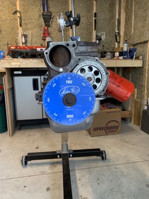
Waiting for my degree wheel to arrive and then I can clock the cam.
View attachment 22915
You are using an out of date browser. It may not display this or other websites correctly.
You should upgrade or use an alternative browser.
You should upgrade or use an alternative browser.
All Small Six My 200 CI mystery
- Thread starter awasson
- Start date
This relates to all small sixes
Well… According to my math, on my engine, at straight up on the timing chain (dot 2 dot), the Clay Smith cam is advanced by 4 degrees. I’ve checked the intake lobe and it should get a reading of 105 degrees but I get a reading of 100.5 degrees.
My numbers are as follows:
Top of Intake Lobe cranked back 50/1000: 52
Top of Intake Lobe cranked forward 50/1000: 149
(52 + 149) / 2 = 100.5 INT
Advertised numbers are 105 so my number is 4.5 degrees advanced. I’ve checked about half a dozen times and checked TDC several times to make certain. Every time I get the same numbers.
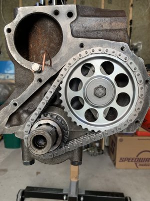
My cam chain has a multi slotted crank gear so I can advance/retard the cam 2, 4, 6, 8 degrees. I think I’ll retard it 4 degrees and recheck my numbers.


Button it up, .5 degree, isnt even within the instrument error, just stick it in as advanced as you can, probably 8 degrees, and go driving, people getting a bit carried away here.
Do not install the cam more advanced than the cam card spec.
It will make the engine more prone to detonation.
We have Instances where the wrong cam was shipped in the box that is labeled correctly.
The marking on your cam indicates it has a 110 LSA which is not the cam you wanted according to your previous posts.
Just to be sure you got the right cam please check your cam timing using the .050” duration method on both the intake and exhaust cam lobes.
I can walk you through the procedure if needed.
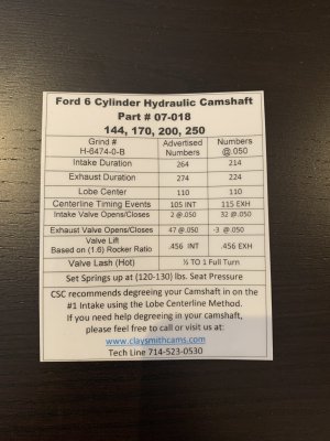
Can you post a picture of your cam card/sheet.
Last edited:
I like to delete the spring adjustment , I find it introduces flex and erroneous readings, your results may very.
Just use the long part of the spring rod, I have some longer rods for when it is to short, there is plenty of adjustment with the other two connection points. Every connection needs to be tight and the base stable.
PS listen to Paul, he is the best cam degreeing guy here. Have him walk you through it.
Do not install the cam more advanced than the cam card spec.
It will make the engine more prone to detonation.
We have Instances where the wrong cam was shipped in the box that is labeled correctly.
The marking on your cam indicates it has a 110 LSA which is not the cam you wanted according to your previous posts.
Just to be sure you got the right cam please check your cam timing using the .050” duration method on both the intake and exhaust cam lobes.
I can walk you through the procedure if needed.
Can you post a picture of your cam card/sheet.
Thanks Paul,
Yes, I am expecting lobe center to be at 110. I decided on the H-6474-0-B camshaft rather than the H-267-8-B. I decided that I wanted a smoother idle and better vacuum for the brakes (adding power brakes).
The cam card that came with the cam has the timing events slightly different than what the CS website shows for that cam so they may have changed the recipe on that grind: https://claysmithcams.com/h-6474-0-b-excellent-mid-range-street-cam-w-2v-carb-ford-144-170-200-250/
I’ll be checking everything over again today and I’ll redo my centerline and I’ll do my duration at 0.50” just to make sure. I’m not in a rush so I can measure and remeasure as often as I need to to get it right.
As I understand it, Clay Smith camshafts are supposed to be ground straight up with no built in advance. The tech article on this site suggests that they are ground straight up and that for street use, it should be advanced 4 degrees. I don’t have an informed opinion on that so I’m open to hearing what the experts have to say on that subject: https://fordsix.com/ams/degreeing-your-camshaft.21/
Thanks for all of the comments on my engine. The last pushrod engine I built was in the mid-1980’s (327 chev) and now I wonder how that thing even ran after I was done with it. My attention to detail was severely lacking compared to this one.
Cheers,
Andrew
Ok… That makes sense. I was wondering why the cam card was different than the example cam card on the Clay Smith page.The cam card indicates that the cam has 5* advance built into it. That's the 105* lobe center with the 110* LSA.
So if I understand that correctly, that means that I do need to make sure that the cam is degree’d straight up according to the card, otherwise I’ll end up with 9 or 10 degrees of advance. I’ll check and double, triple check my numbers today and if necessary retard the cam to make it match the cam card.
Engine Fan
Well-known member
Retard it 4 degrees from where it is like you are thinking.Well… According to my math, on my engine, at straight up on the timing chain (dot 2 dot), the Clay Smith cam is advanced by 4 degrees. I’ve checked the intake lobe and it should get a reading of 105 degrees but I get a reading of 100.5 degrees.
My numbers are as follows:
Top of Intake Lobe cranked back 50/1000: 52
Top of Intake Lobe cranked forward 50/1000: 149
(52 + 149) / 2 = 100.5 INT
Advertised numbers are 105 so my number is 4.5 degrees advanced. I’ve checked about half a dozen times and checked TDC several times to make certain. Every time I get the same numbers.
My cam chain has a multi slotted crank gear so I can advance/retard the cam 2, 4, 6, 8 degrees. I think I’ll retard it 4 degrees and recheck my numbers.
View attachment 22927View attachment 22928View attachment 22929
Then verify your opening and closing events @.050' lift to verify the cam is what its supposed to be like Paul said.
The cam card says that with the timing chain in "neutral" the cam will be 5* advanced relative to piston position. A cam that is "straight up" with no advance relative to the piston, the lobe center is the same as the lobe separation angle, or 110* on you cam. With the lobe center @ 105*, the cam is advanced 5*. So yes, if you button it up @ 100* lobe center the cam is 10* advanced, that's too much. Don't worry about why it's off. Many are, this is why we degree them. My last build the cam was off 5* from the card AND the 4* advance in the timing gear was actually 6*.Ok… That makes sense. I was wondering why the cam card was different than the example cam card on the Clay Smith page.
So if I understand that correctly, that means that I do need to make sure that the cam is degree’d straight up according to the card, otherwise I’ll end up with 9 or 10 degrees of advance. I’ll check and double, triple check my numbers today and if necessary retard the cam to make it match the cam card.
Using the .050" lift points is more accurate than finding the top of the lobe. It will also verify that the cam has the duration it claims. Also it is imperative that your degree wheel is accurate relative to TDC.
The card is indicating that the cam should be advanced 5 degrees which would put the intake lobe center at 105 degrees ATDC and the exhaust lobe center at 115 degrees BTDC.Ok… That makes sense. I was wondering why the cam card was different than the example cam card on the Clay Smith page.
So if I understand that correctly, that means that I do need to make sure that the cam is degree’d straight up according to the card, otherwise I’ll end up with 9 or 10 degrees of advance. I’ll check and double, triple check my numbers today and if necessary retard the cam to make it match the cam card.
If you look at the cam card it gives you the four .050" duration points that you need to check that will indicate the cam is 5 degrees advanced.
Intake opening .050" lobe lift at 2 degrees BTDC.
Intake closing .050" lobe lift at 32 degrees ABDC
Exhaust opening .050" lobe lift at 47 degrees BBDC
Exhaust closing .050" lobe lift at 3 degrees BTDC
Retard the cam six degrees from where it is now and do the following.
Set the cam with the intake lifter all the way down on the heel of the cam then zero the dial indicator.
Turn the crankshaft clockwise until the intake lifter raises to .050" and record the reading from the degree wheel.
Then turn the crankshaft clockwise until the intake lifter is .050" from returning to the bottom and record the degree wheel reading.
Do the same for the exhaust lifter.
Report your readings here and we can calculate cam timing for both intake and exhaust along with .050" durations and LSA.
The card is indicating that the cam should be advanced 5 degrees which would put the intake lobe center at 105 degrees ATDC and the exhaust lobe center at 115 degrees BTDC.
If you look at the cam card it gives you the four .050" duration points that you need to check that will indicate the cam is 5 degrees advanced.
Intake opening .050" lobe lift at 2 degrees BTDC.
Intake closing .050" lobe lift at 32 degrees ABDC
Exhaust opening .050" lobe lift at 47 degrees BBDC
Exhaust closing .050" lobe lift at 3 degrees BTDC
Retard the cam six degrees from where it is now and do the following.
Set the cam with the intake lifter all the way down on the heel of the cam then zero the dial indicator.
Turn the crankshaft clockwise until the intake lifter raises to .050" and record the reading from the degree wheel.
Then turn the crankshaft clockwise until the intake lifter is .050" from returning to the bottom and record the degree wheel reading.
Do the same for the exhaust lifter.
Report your readings here and we can calculate cam timing for both intake and exhaust along with .050" durations and LSA.
I've just started from scratch again, checked and double checked using lobe center and my numbers are consistent with each other at 50/1000 and 30/1000 and if I add my INT + EXH and divide by 2 I get my 110 lobe center. I actually get 110.25 so pretty close and within a reasonable margin of error.
I have to run out and exercise the pup and then I'll retard it 6 degrees, do the heel measurements at .050" and report my findings.
Also... My math from yesterday was wrong. It was consistent but wrong. I was reading the wheel 10 degrees wrong each time so it is closer to 10 degrees advanced than 6.
INT
-50/1000 = 51.5
+50/1000 = 139.5
(51.5+139.5)/2 = 95.5
EXH
-50/1000 = 171
+50/1000 = 79
(171+79)/2 = 125
LOBE CENTER
(95.5+125)/2 = 110.25
I've already retarded it 4 and the numbers are consistent
INT
-50/1000 = 55.5
+50/1000 = 143.5
(55.5+143.5)/2 = 99.5
EXH
-50/1000 = 167
+50/1000 = 75
(167+75)/2 = 121
LOBE CENTER
(99.5+121)/2 = 110.25
I'll still retard it 6 degrees as suggested and do the heel measurements at .050" and then I can go from there. At least that will confirm or refute my other readings.
INT
-50/1000 = 51.5
+50/1000 = 139.5
(51.5+139.5)/2 = 95.5
EXH
-50/1000 = 171
+50/1000 = 79
(171+79)/2 = 125
LOBE CENTER
(95.5+125)/2 = 110.25
I've already retarded it 4 and the numbers are consistent
INT
-50/1000 = 55.5
+50/1000 = 143.5
(55.5+143.5)/2 = 99.5
EXH
-50/1000 = 167
+50/1000 = 75
(167+75)/2 = 121
LOBE CENTER
(99.5+121)/2 = 110.25
I'll still retard it 6 degrees as suggested and do the heel measurements at .050" and then I can go from there. At least that will confirm or refute my other readings.
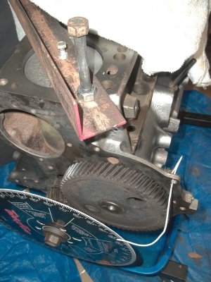
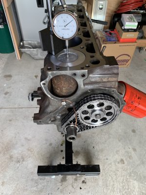
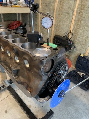
I am 100% certain that it is at TDC within some very small margin of error. I've puled it apart and put it back together several times and reset my TCD several times.How sure are you about the degree wheel being at zero with the piston at TDC
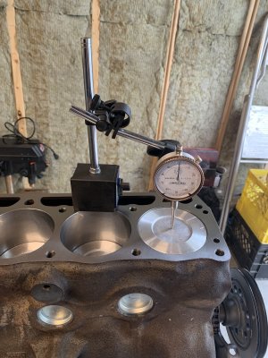
I've started with the dot's lined up, to get in the ballpark, without the degree wheel on. Then I used my dial indicator on the middle of the piston top to get it to TDC (using the balancer to twist it back and forwards, always ending on a forward turn). Then, I've installed the wheel (with the dial indicator still in place) and used my 13/16" wrench to get to TDC. Then I've lined up my marker for absolute TDC on the wheel and turned back 10/1000 and forwards 10" to split the difference to check and make sure I'm in the middle of the dwell. I think measured back 10/1000 it was 6 degrees and forwards 10/1000 was 6 degrees.
Sounds like you've been real careful and precise finding it. A piston stop is a sure way too.I'm back now so I'll do the heel measurements at .050" after lunch and report back.
I'll take plenty of photos to show where my TDC is in case I'm missing something fundamental.
Attachments
The correct way is to install the degree wheel first and get the wheel pointer close to TDC with the piston at TDC.I used my dial indicator on the middle of the piston top to get it to TDC (using the balancer to twist it back and forwards, always ending on a forward turn)
Then zero the dial indicator and turn the crank clockwise until the piston goes down and back up to .050" before TDC and note the reading on the wheel.
Then turn the crank counterclockwise until the piston goes down and back up to .050" from TDC.
Note the wheel reading.
If the degree wheel is pointer is set at TDC, both the two reading should be the same.
Let's say one reading is 13 degrees before TDC and the other is 11 degrees after TDC.
Then bend the pointer to 12 degrees before TDC and check it again and adjust until both readings are the same.
Last edited:
Similar threads
All Small Six
Help. Need a 200 inline 6 for my 1968 mustang
- Replies
- 2
- Views
- 255
All Small Six
200 rebuild.
- Replies
- 1
- Views
- 209
- Replies
- 20
- Views
- 1K
- Replies
- 6
- Views
- 465
- Replies
- 0
- Views
- 342

