You are using an out of date browser. It may not display this or other websites correctly.
You should upgrade or use an alternative browser.
You should upgrade or use an alternative browser.
All Small Six Back in the Saddle
- Thread starter cr_bobcat
- Start date
-
- Tags
- boneheaded_ideas
This relates to all small sixes


On a 300 six the front of the camshaft's front bearing journal is even with the front of the block.They do appear to be ever so slightly biased. I also took pics of how I have the cam installed. I centered it on the bearings because I don't have it torqued into place.
Since your engine uses a thrust plate the front of the camshaft should also be flush with the front of the block
Last edited:


The cam lobes are definitely offset.Here is a shot from the assembled 200 I have sitting around
Please measure the first two lifter bore locations.
Install a stock lifter in the first lifter bore and measure from the side of the lifter to the front of the block.
What is that measurement?

Next install the stock lifter in the second lifter bore and measure from the side of the lifter to the front of the engine block.
What is that measurement?

Add 1/2 the lifter diameter to those two measurements to get the lifter bore center locations from the front of the block.
Install a stock lifter in the first lifter bore and measure from the side of the lifter to the front of the block.
What is that measurement?
Next install the stock lifter in the second lifter bore and measure from the side of the lifter to the front of the engine block.
What is that measurement?
Add 1/2 the lifter diameter to those two measurements to get the lifter bore center locations from the front of the block.
Last edited:
Next measure the first cam lobe location from the back side of the cam lobe to the front of the cam journal.
Then subtract 1/2 the width of the cam lobe to get the lobe center location from the front of the cam.

Then measure the second cam lobe location from the back side of the second cam lobe to the front of the cam journal.
Then subtract 1/2 the width of that cam lobe to get the lobe center location from the front of the cam.

What measurements did you get?
The difference between lifter bore centers and the cam lobe centers from the front of the block will be the roller cam lobe offset needed to make roller cams.
The roller cam lobes for the 240/300 roller cams had to be repositioned .095" back from the flat tappet cam lobe locations.
Then subtract 1/2 the width of the cam lobe to get the lobe center location from the front of the cam.
Then measure the second cam lobe location from the back side of the second cam lobe to the front of the cam journal.
Then subtract 1/2 the width of that cam lobe to get the lobe center location from the front of the cam.
What measurements did you get?
The difference between lifter bore centers and the cam lobe centers from the front of the block will be the roller cam lobe offset needed to make roller cams.
The roller cam lobes for the 240/300 roller cams had to be repositioned .095" back from the flat tappet cam lobe locations.
Attachments
Last edited:
I'll take a look this week. Was at a Cub Scout campout this past weekend.Next measure the first cam lobe location from the back side of the cam lobe to the front of the cam journal.
Then subtract 1/2 the width of the cam lobe to get the lobe center location from the front of the cam.
View attachment 29240
Then measure the second cam lobe location from the back side of the second cam lobe to the front of the cam journal.
Then subtract 1/2 the width of that cam lobe to get the lobe center location from the front of the cam.
View attachment 29242
What measurements did you get?
The difference between lifter bore centers and the cam lobe centers from the front of the block will be the roller cam lobe offset needed to make roller cams.
The roller cam lobes for the 240/300 roller cams had to be repositioned .095" back from the flat tappet cam lobe locations.
No pressure on this but, any more head way?
Not yet. Monday I had to drive my kid to soccer practice 1.5 hr away and last night we had Cub Scout meetings. Kids and their schedules have been a major damper on my progress. I was able to get a bunch done the previous weeks because I had to work from home a number of days. I'm hoping to get out there tonight while my daughter is at dance. Fingers crossed.....No pressure on this but, any more head way?

Your children are an investment of infinite value. Relatively- "stuff", including classic cars/engines, is nothing. (When old enough, they can be incorporated into assisting with the mechanic work. Accomplishes quality time, and they learn a valuable skill while you get your projects done. Win-win. ") )
)
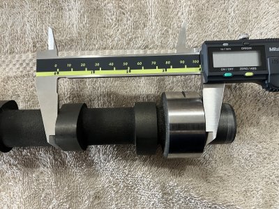
)I took some measurements last night. I didn't like my numbers as it didn't seem consistent. I'm going to re-do it when I get home from work. I think I must've bumped the caliper when trying to take a picture or something. That said, I think the offset you quoted for the 300 is going to be pretty similar to what the 200/250 will be. Which makes sense - they both use 0.875" hydro lifters. If the lifters have to spin by using an offset, it's likely the same offset... But anyway, will know tonight.
I took some measurements last night. I didn't like my numbers as it didn't seem consistent. I'm going to re-do it when I get home from work. I think I must've bumped the caliper when trying to take a picture or something. That said, I think the offset you quoted for the 300 is going to be pretty similar to what the 200/250 will be. Which makes sense - they both use 0.875" hydro lifters. If the lifters have to spin by using an offset, it's likely the same offset... But anyway, will know tonight.
Thanks for doing all of the leg work on this. I am following eagerly. I wasn't intending on pulling my camshaft any time soon but... you never know. If this can be fitted in a 200 then it will definitely go on my todo list.
Hey, slightly off topic for just a moment... I see from your signature you are running a similar setup on your 200 to what I will have once I install the C9 head with the bigger valves. I see you're running HEI with 20° initial advance on manifold vacuum. I'm running 24° initial on manifold with an HEI (I might pull mine back just a touch). Do you recall what springs are you using on your mechanical advance? I'm using silver on mine currently and if I drop my initial timing, I'll probably go with the lighter gold springs.
I did measure the offset of 3 lobes on a 200 and 250, and they where not what was expected. So I think I made an error, be nice to see what you come up with.
Yes, See post #85 and 86 above.would it be easier to remove cam.
drop lifter in
measure to edge of lifter from front of block
add 1/2 lifter diameter
See post # 85 and 86 above.I did measure the offset of 3 lobes on a 200 and 250, and they where not what was expected. So I think I made an error, be nice to see what you come up with.
Please use that same procedure.
Ignore this if you are already doing so.


Great Job taking measurements!
Thank You
After doing the math it looks like the cam lobe centers are .050" towards the back of the block from the lifter bore centers.
The 300 six cam lobe centers are .095" towards the front of the block from the lifter bore centers.
The difference in offset directions is probably because the 300 camshaft rotates in the opposite direction from the small block six.
Last edited:
Similar threads
- Replies
- 26
- Views
- 3K
All Small Six
Camshaft Degree Troubleshooting Help
- Replies
- 30
- Views
- 8K